2013 March 19: Install the left cylinder head
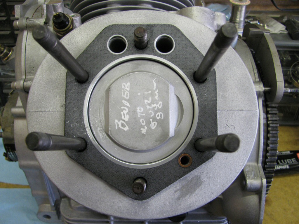
Photo courtesy of Gregory Bender.
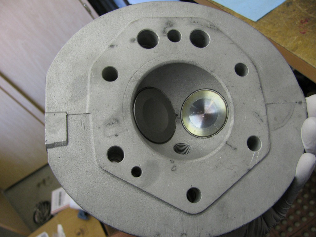
Photo courtesy of Gregory Bender.
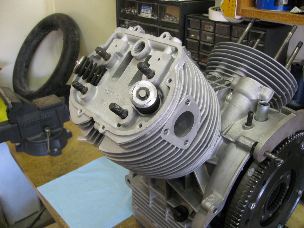
Photo courtesy of Gregory Bender.
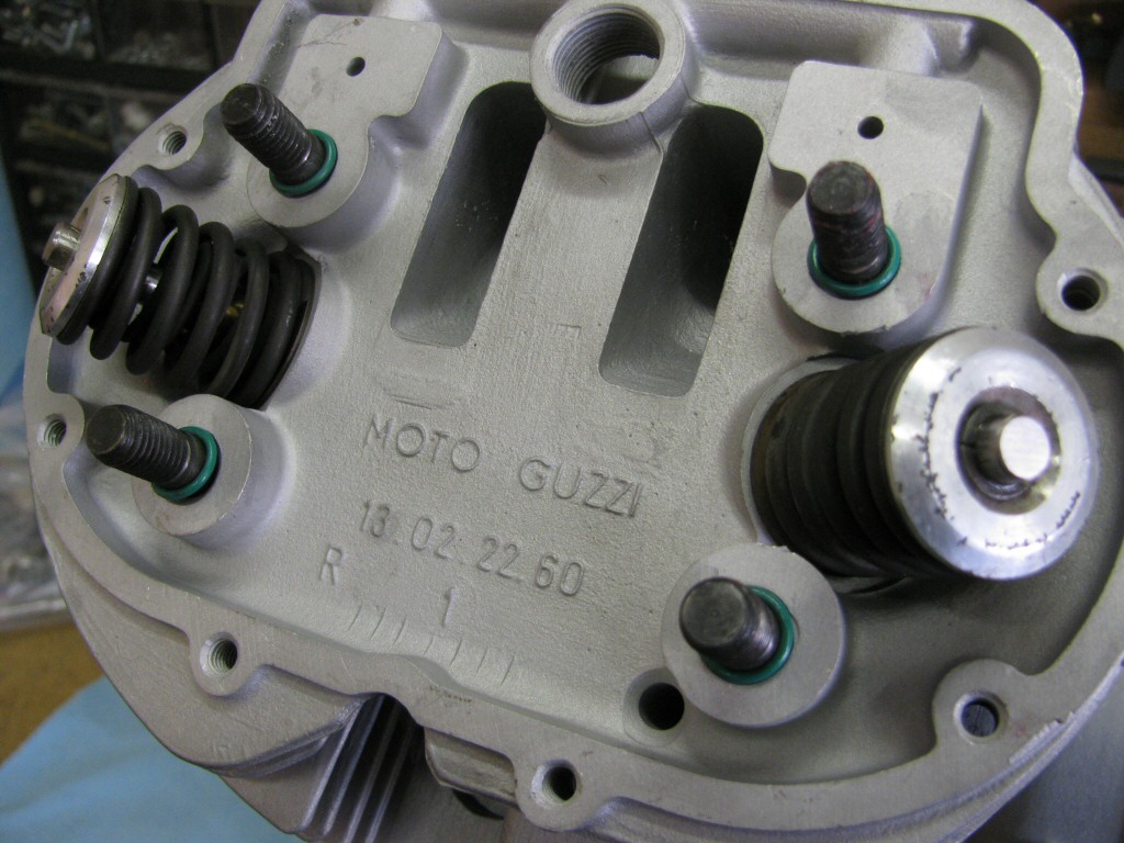
Photo courtesy of Gregory Bender.
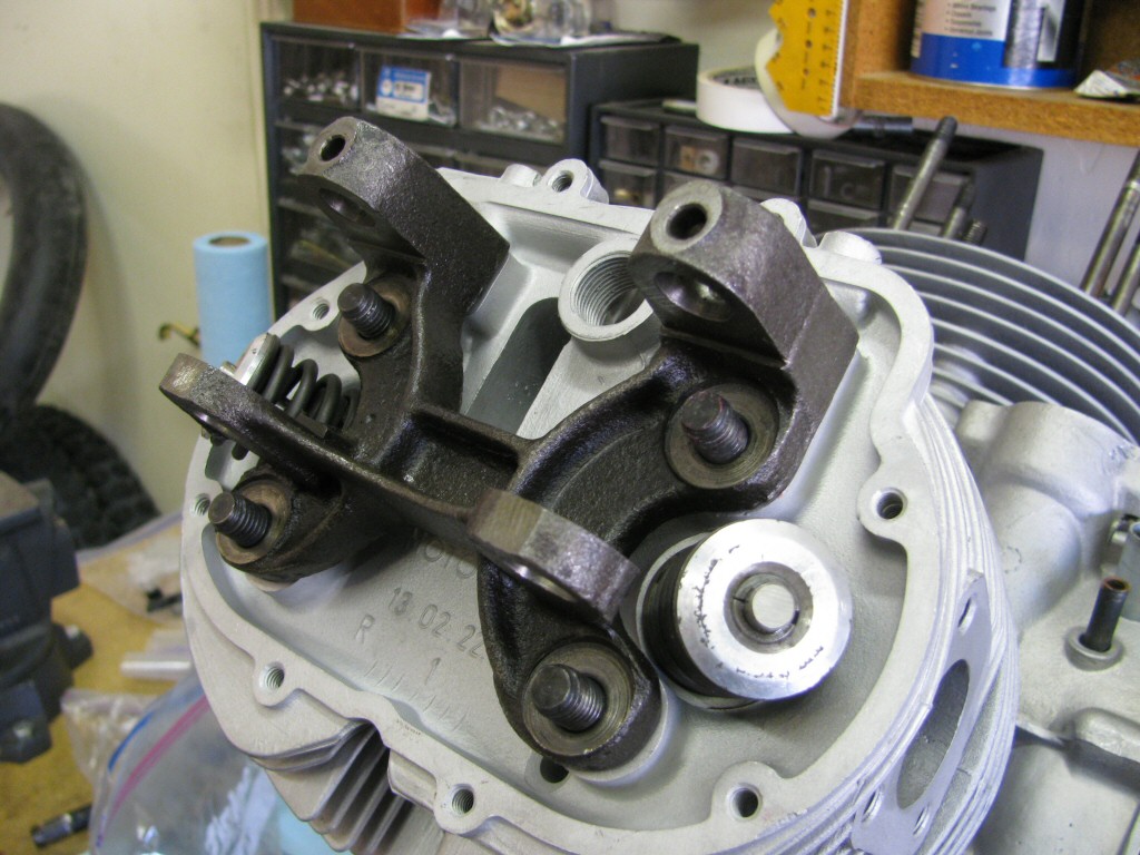
Photo courtesy of Gregory Bender.
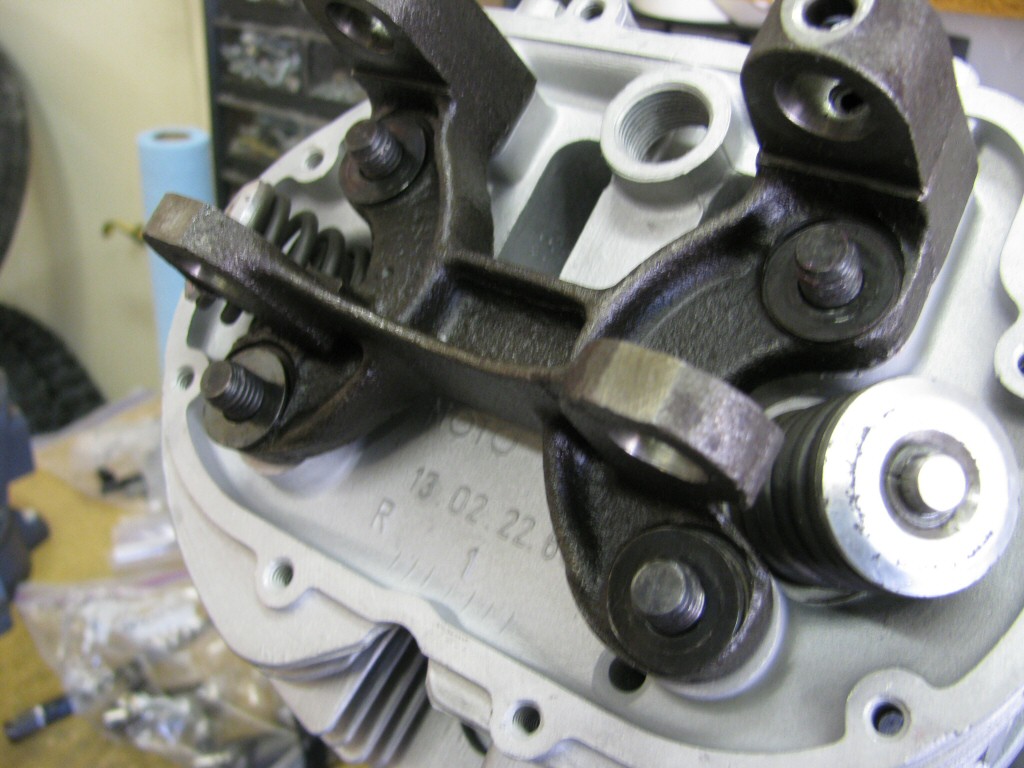
Photo courtesy of Gregory Bender.
6 o'clockstud.
Photo courtesy of Gregory Bender.
12 o'clockstud.
Photo courtesy of Gregory Bender.
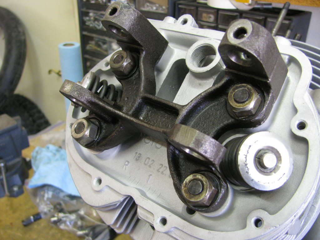
Photo courtesy of Gregory Bender.
12 o'clockand
6 o'clocknuts.
Photo courtesy of Gregory Bender.
Photo courtesy of Gregory Bender.
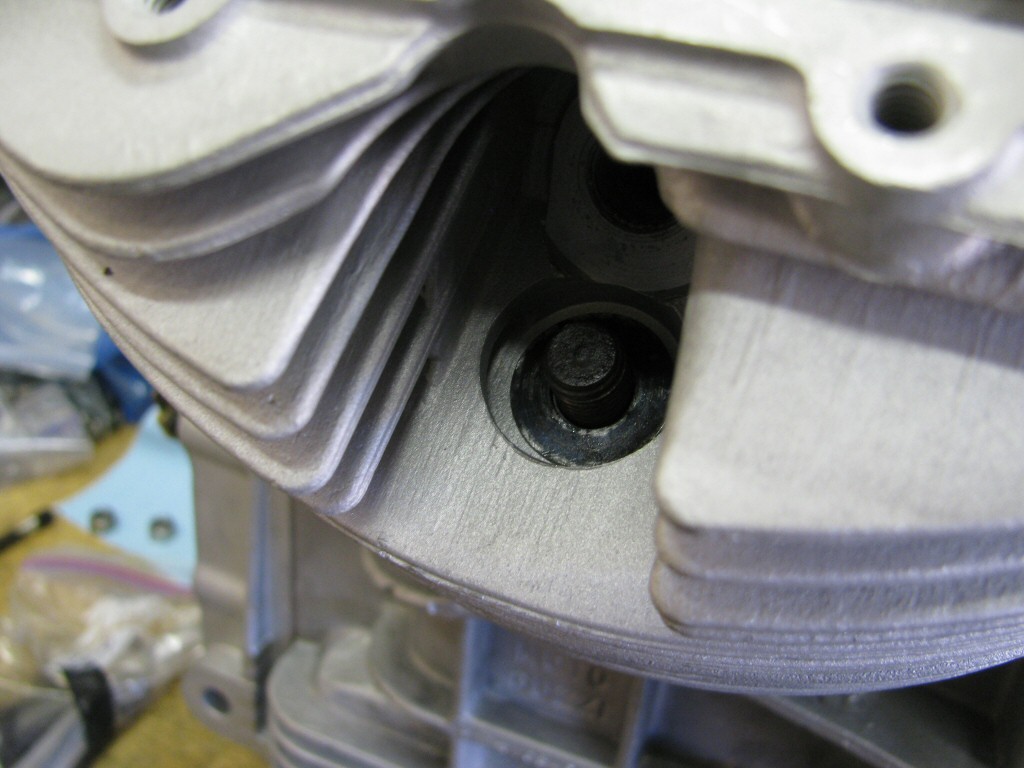
12 o'clocknut access hole.
Photo courtesy of Gregory Bender.
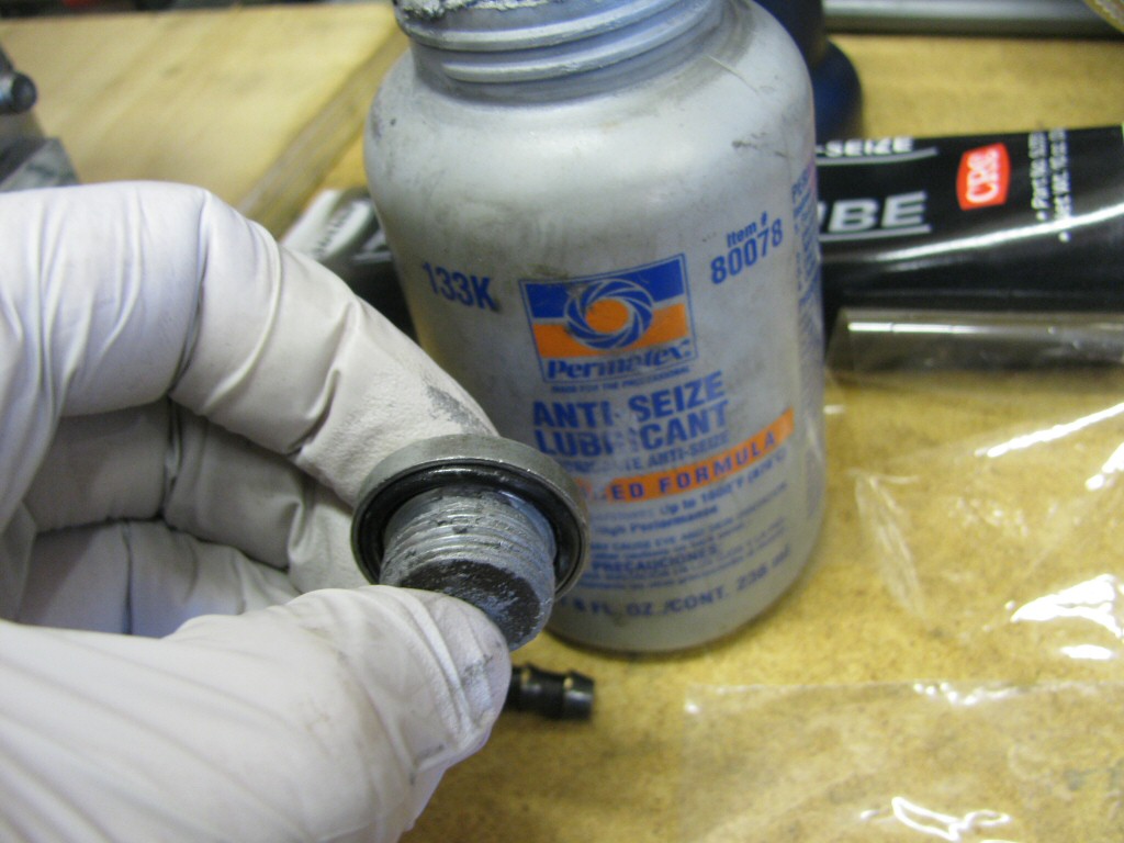
Photo courtesy of Gregory Bender.
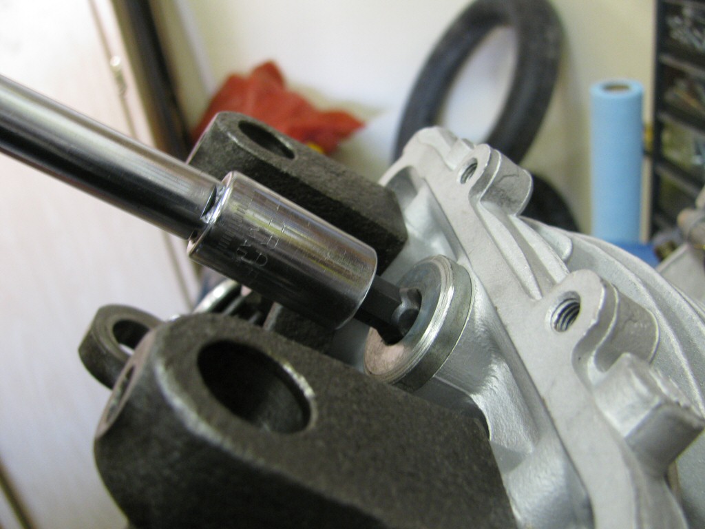
Photo courtesy of Gregory Bender.
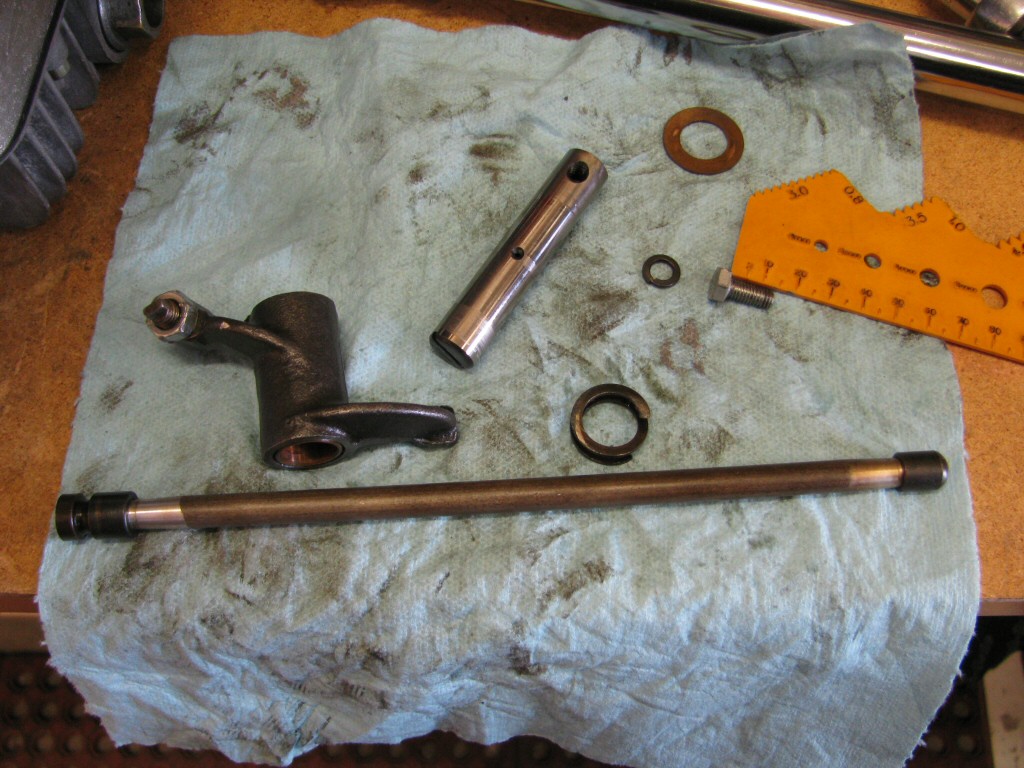
Photo courtesy of Gregory Bender.
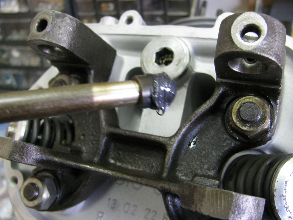
Photo courtesy of Gregory Bender.
Photo courtesy of Gregory Bender.
Photo courtesy of Gregory Bender.
Photo courtesy of Gregory Bender.
Photo courtesy of Gregory Bender.
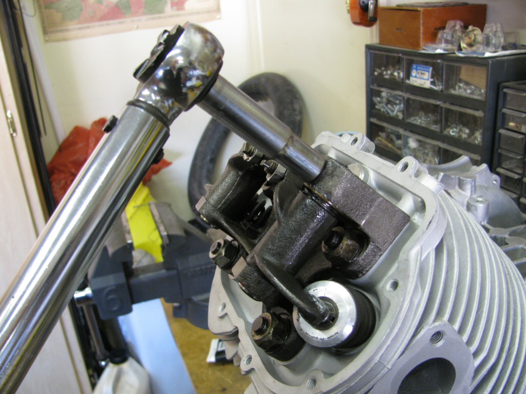
Photo courtesy of Gregory Bender.
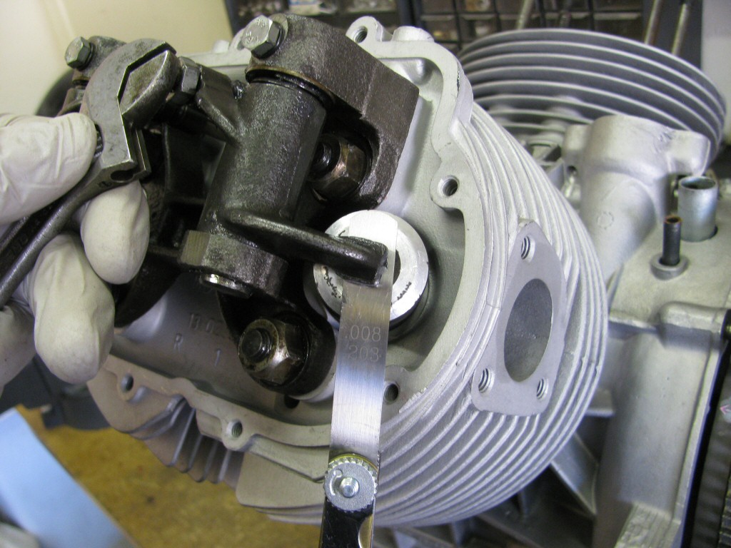
Photo courtesy of Gregory Bender.
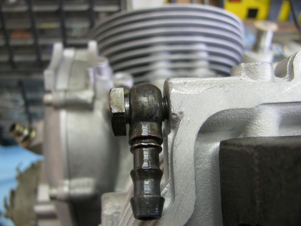
Photo courtesy of Gregory Bender.