Moto Guzzi V7 Sport, 750 S, 750 S3, 850 T, 850 T3, 850 T3 California, V1000 I-Convert, V1000 G5, 1000 SP, Le Mans, Le Mans II, Le Mans CX 100, Le Mans III, Le Mans 1000, 1000 SP III, 1000 S, California II, California III, California III Fuel Injection, California III Full Fairing, California 1100, California Jackal, California EV, California EV Touring, California Aluminium, California Titanium, California Special, California Special Sport, California Stone-Metal, California Stone-Touring, California Classic, California Touring, and California Vintage models
Created:
Updated:
Instructions specific to Moto Guzzis
U-joint rebuild and installation
Thanks to Kim Anderson for sending me this information via email. In Kim's own words and photos:
I've just had to rebuild two small unijoints and had found available info a bit hard to follow. There were a few technical diagrams, and dozens of videos, often starring burly men swinging large hammers with an arc that would impress Greg Norman, but nothing suitable for the very compact UJ's on early Tonti's. I have made a two page (and larger 3 page article) on how I've done it. With a few photos.
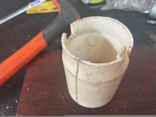
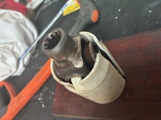
I also made a UJ installer that worked like a dream. It's not completely dissimilar to the one on your website but it took less than two minutes to make. A photo is attached here with a UJ installed. To make it I cut three slots in the bell end of a 2 inch inch PVC pipe, bent over two ears with a heatgun and they perfectly grab the side caps on the yoke of the uj, and the central yoke or body is held very stiffly in the split tube. I've never had such an easy go at installing UJ's. The article on rebuilding uj's needs a bit of compacting due to the photos so it will take me a while to work this out. What do you reckon?
All joints are fully dismantable and designed for dismantling without special tools.
However for safety reasons, the following work should be carried out only by competent work shops. In case of doubt please ask us.
When dismantling a propeller shaft, first check whether the positions of forks 1 and 2 are marked by arrows (see Fig. 2); if the marking is covered with paint, these sliding parts should be clearly marked together.
We strongly recommend not replacing damaged bearings individually as in most cases the pins on the universal joint will also be damaged. It is therefore advisable to replace only complete universal joint fittings (Fig. 7). In the case of wear in the sliding profile, splined shafts and hubs should always be replaced together. The wear limit for fast running shafts is achieved when play is perceptible in the installed position.
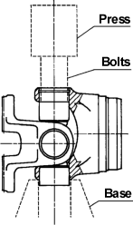
Push the universal joint and bushes to one side using a press (see Fig. 8a).
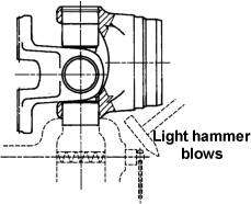
Clamp the projecting bush in a screw vice and withdraw the bush with light hammer blows on the fork (Fig. 8b). Do not reuse bearing bushes with thin walls.
Press in the bearing bushes exactly in line with their centrelines, without tilting them.
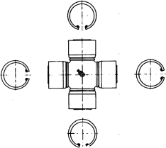
Fit circlips so that the universal joint can be easily moved. To achieve this, circlips of various thickness are used and if absolutely necessary a thicker circlip can be ground to the required dimension. The clearence at the ends of the pins should be adjusted so that the bending moment of the flange in both axes does not exceed 4 Nm, without letting the flange drop down on his own accord.
Check that the joint runs true. To do this, mount the propeller shaft on the flange fitting and check the tube with a dial gauge. Maximum permissible runout is 0.1 mm. For running speeds under 1500 RPM this check will in most cases avoid the need for balancing and for speeds above 1500 RPM it considerably shortens the balancing process.
In the case of motor vehicles, the running speed is generally above 1500 RPM. Propeller shafts for this application must be dynamically balanced. The balancing speed should always be 10-15% above the maximum speed occurring in service.
The acceptable balance is laid out in DIN ISO 1940.