Police 3: Battery cable to the starter along with ancillary wires to voltage regulator and ignition switch
Applicable to these part numbers:
Connections - Magneti Marelli mechanical voltage regulator
- The thick battery cable gets routed down to the left side of the transmission near the starter. I always route this wire between the battery tray and the rear fender in the little
triangle
space that is available there. I route the wires straight down and above the swing arm member, and then route them forward toward the starter area. - The thick battery cable crimped with the two red wires is connected to the positive terminal on the battery. Note: The battery ground cable should NOT be connected to the battery at this time.
- Connect the heavy gauge black battery cable to the 8 mm post terminal at the rear of the starter solenoid. Secure the battery cable to the longer of the two 8 mm posts, located furthest from the body of the starter. As a sanity check, this should be the terminal that does NOT have a very short connection wire directly into the body of the starter.
- The red wire with the 4 mm male bullet terminal is plugged into terminal 30/30 on the ignition switch.
- The other red wire is connected to the voltage regulator
- The red wire with the 6 mm ring terminal is secured to the bottom left lug (bottom as in nearest to the ground, left as when seated properly astride the motorcycle).
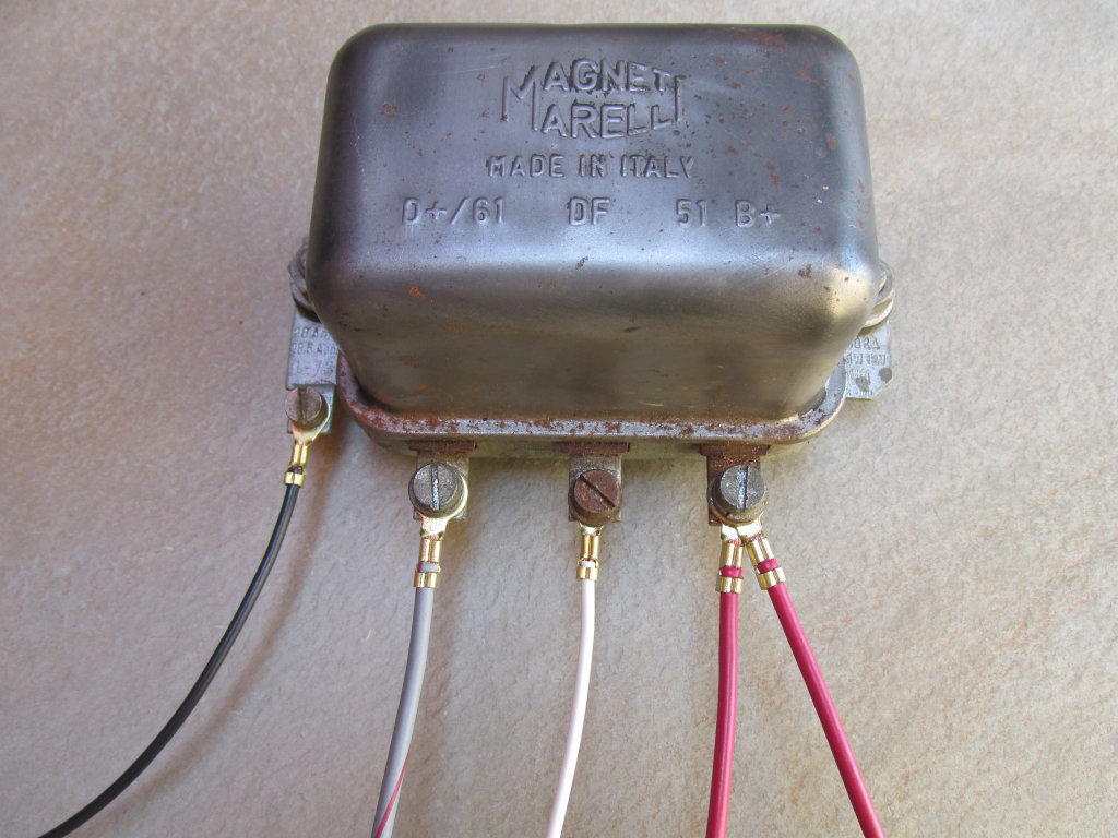
Photo courtesy of Gregory Bender.
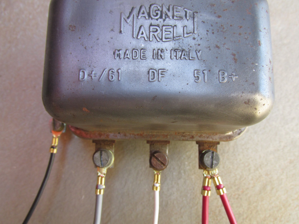
Photo courtesy of Gregory Bender.
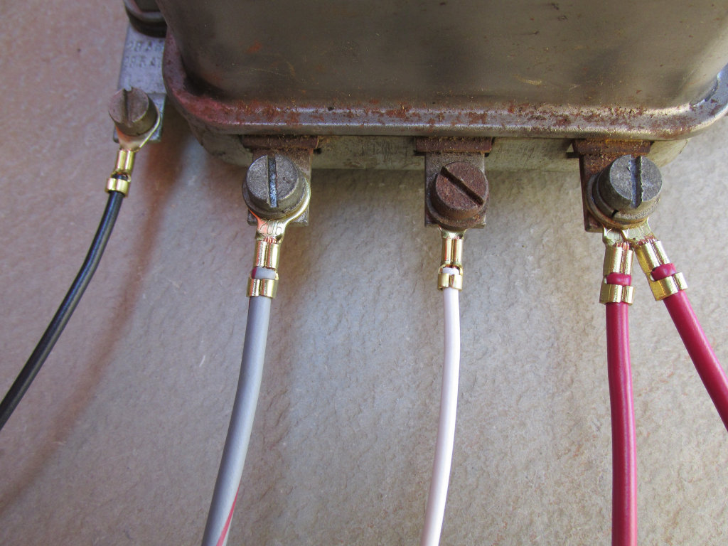
Photo courtesy of Gregory Bender.
Connections - Aftermarket Echlin mechanical voltage regulator to fit Magneti Marelli charging systems.
Warning:
The wire positions differ from the original Magneti Marelli voltage regulator!
- The thick battery cable gets routed down to the left side of the transmission near the starter. I always route this wire between the battery tray and the rear fender in the little
triangle
space that is available there. I route the wires straight down and above the swing arm member, and then route them forward toward the starter area. - The thick battery cable crimped with the two red wires is connected to the positive terminal on the battery. Note: The battery ground cable should NOT be connected to the battery at this time.
- Connect the heavy gauge black battery cable to the 8 mm post terminal at the rear of the starter solenoid. Secure the battery cable to the longer of the two 8 mm posts, located furthest from the body of the starter. As a sanity check, this should be the terminal that does NOT have a very short connection wire directly into the body of the starter.
- The red wire with the 4 mm male bullet terminal is plugged into terminal 30/30 on the ignition switch.
- The other red wire is connected to the voltage regulator
- The red wire with the 6 mm ring terminal is secured to the bottom right lug (bottom as in nearest to the ground, right as when seated properly astride the motorcycle).
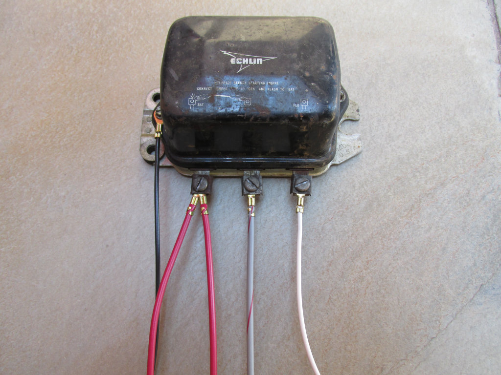
Photo courtesy of Gregory Bender.
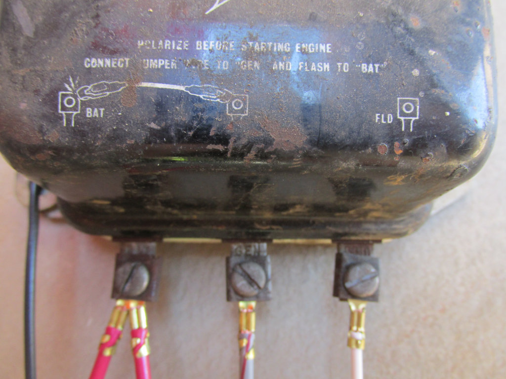
Photo courtesy of Gregory Bender.
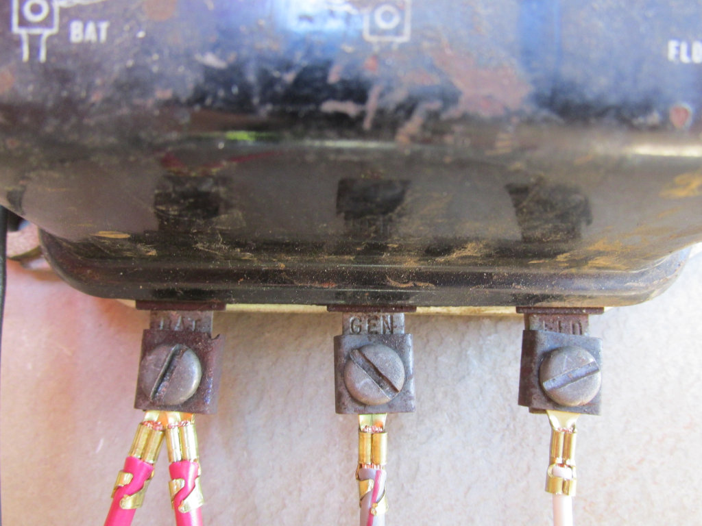
Photo courtesy of Gregory Bender.
Connections - Unknown aftermarket mechanical voltage regulator to fit Magneti Marelli charging systems.
Warning:
The wire positions differ from the original Magneti Marelli voltage regulator!
- The thick battery cable gets routed down to the left side of the transmission near the starter. I always route this wire between the battery tray and the rear fender in the little
triangle
space that is available there. I route the wires straight down and above the swing arm member, and then route them forward toward the starter area. - The thick battery cable crimped with the two red wires is connected to the positive terminal on the battery. Note: The battery ground cable should NOT be connected to the battery at this time.
- Connect the heavy gauge black battery cable to the 8 mm post terminal at the rear of the starter solenoid. Secure the battery cable to the longer of the two 8 mm posts, located furthest from the body of the starter. As a sanity check, this should be the terminal that does NOT have a very short connection wire directly into the body of the starter.
- The red wire with the 4 mm male bullet terminal is plugged into terminal 30/30 on the ignition switch.
- The other red wire is connected to the voltage regulator
- The red wire with the 9.5 mm female spade terminal is plugged onto the bottom left lug (bottom as in nearest to the ground, left as when seated properly astride the motorcycle).
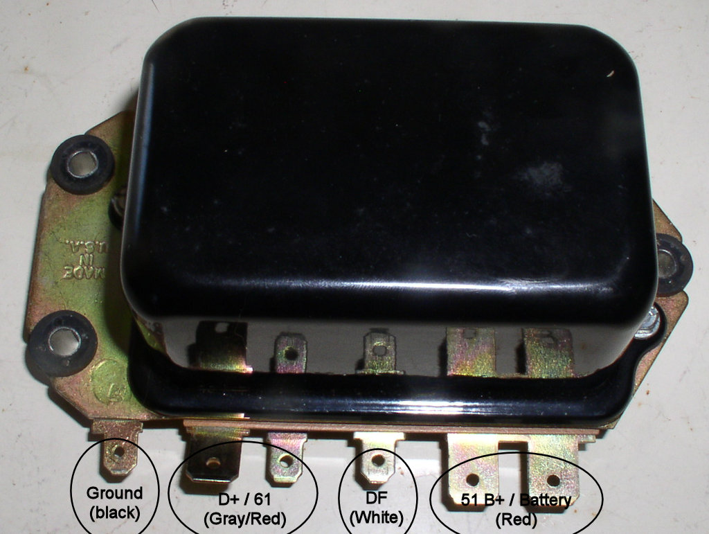
Photo courtesy of Charlie Mullendore of Antietam Classic Cycle.
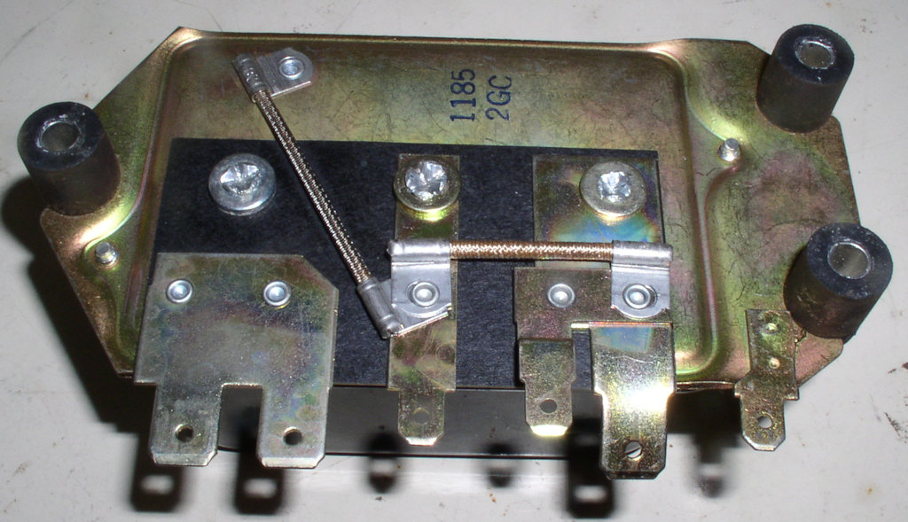
Photo courtesy of Charlie Mullendore of Antietam Classic Cycle.
Connections - Bosch mechanical voltage regulator
- The thick battery cable gets routed down to the left side of the transmission near the starter. I always route this wire between the battery tray and the rear fender in the little
triangle
space that is available there. I route the wires straight down and above the swing arm member, and then route them forward toward the starter area. - The thick battery cable crimped with the two red wires is connected to the positive terminal on the battery. Note: The battery ground cable should NOT be connected to the battery at this time.
- Connect the heavy gauge black battery cable to the 8 mm post terminal at the rear of the starter solenoid. Secure the battery cable to the longer of the two 8 mm posts, located furthest from the body of the starter. As a sanity check, this should be the terminal that does NOT have a very short connection wire directly into the body of the starter.
- The red wire with the 4 mm male bullet terminal is plugged into terminal 30/30 on the ignition switch.
- The other red wire is connected to the voltage regulator
- The red wire with the 9.5 mm female spade terminal is plugged onto the top left lug (top as in furthest from the ground, left as when seated properly astride the motorcycle).
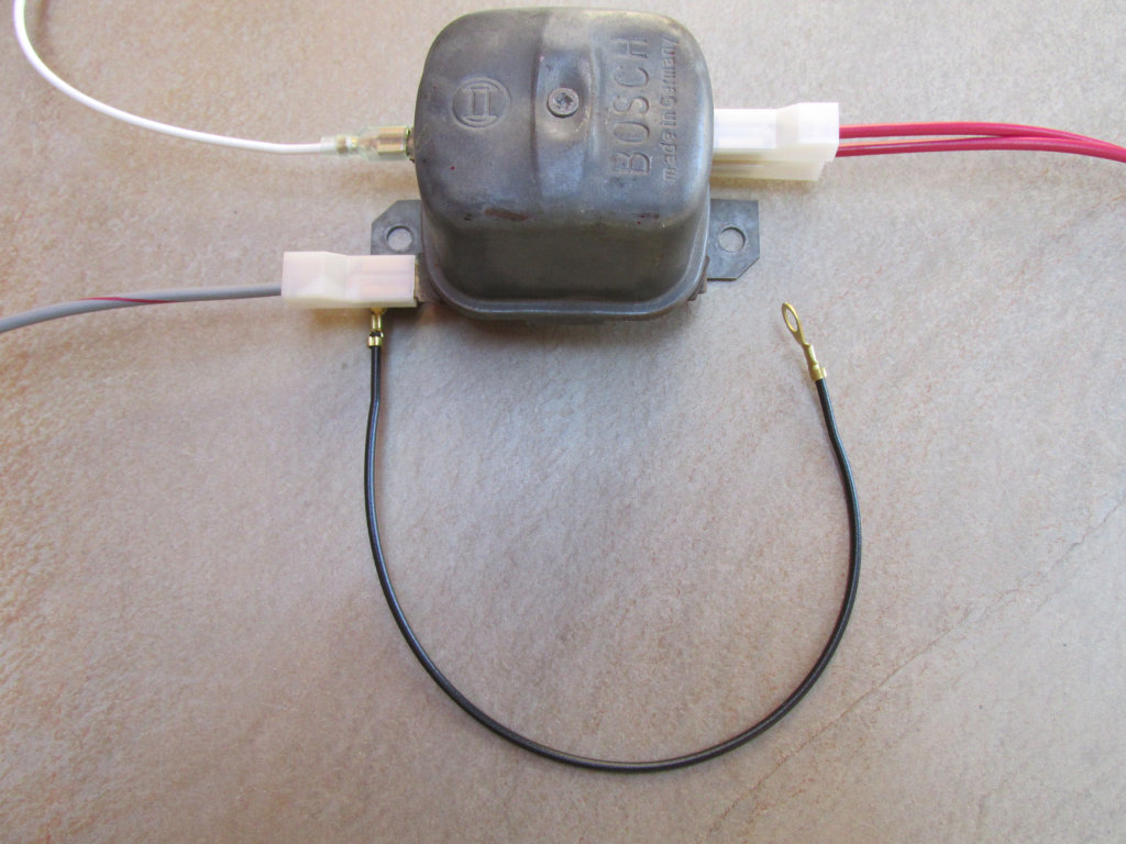
Photo courtesy of Gregory Bender.
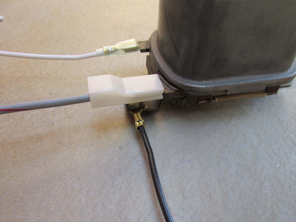
Photo courtesy of Gregory Bender.
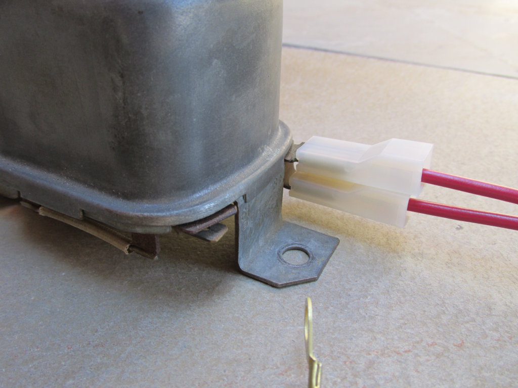
Photo courtesy of Gregory Bender.
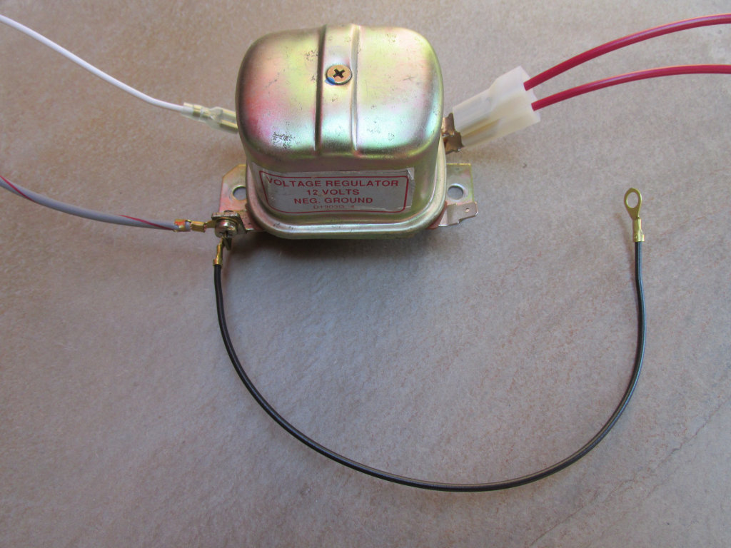
Photo courtesy of Gregory Bender.
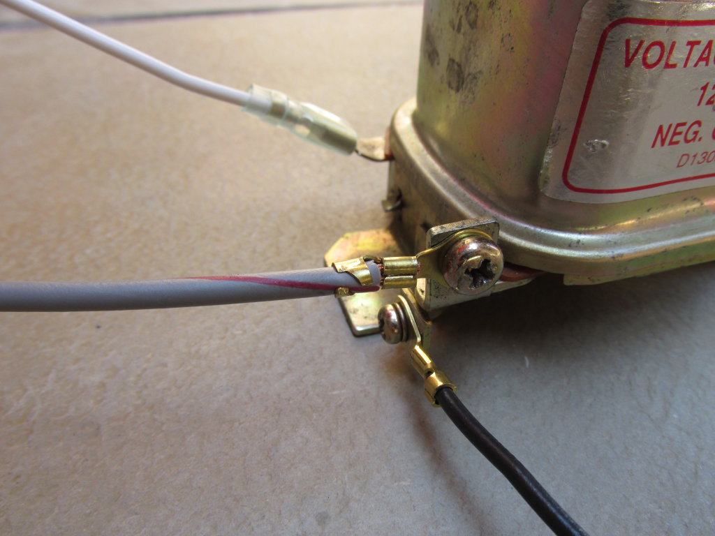
Photo courtesy of Gregory Bender.
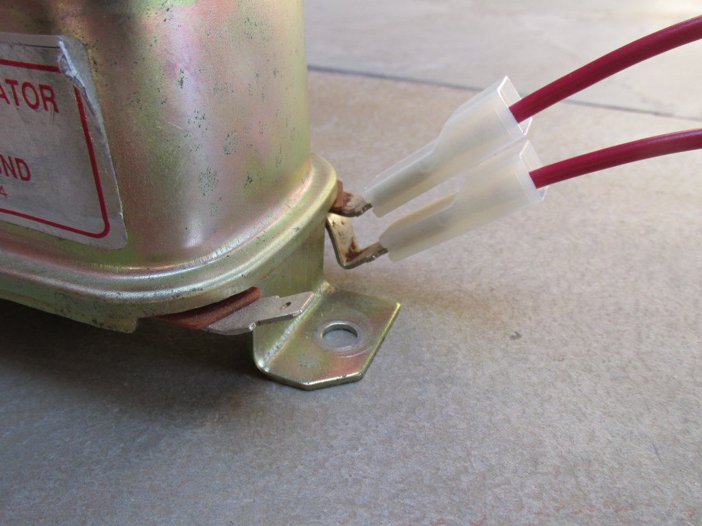
Photo courtesy of Gregory Bender.
Connections - Bosch electronic voltage regulator
- The thick battery cable gets routed down to the left side of the transmission near the starter. I always route this wire between the battery tray and the rear fender in the little
triangle
space that is available there. I route the wires straight down and above the swing arm member, and then route them forward toward the starter area. - The thick battery cable crimped with the two red wires is connected to the positive terminal on the battery. Note: The battery ground cable should NOT be connected to the battery at this time.
- Connect the heavy gauge black battery cable to the 8 mm post terminal at the rear of the starter solenoid. Secure the battery cable to the longer of the two 8 mm posts, located furthest from the body of the starter. As a sanity check, this should be the terminal that does NOT have a very short connection wire directly into the body of the starter.
- The red wire with the 4 mm male bullet terminal is plugged into terminal 30/30 on the ignition switch.
- The other red wire is connected to the voltage regulator
- The red wire with the 9.5 mm female spade terminal is plugged onto the top left lug marked
B+
(top as in furthest from the ground, left as when seated properly astride the motorcycle).
- The red wire with the 9.5 mm female spade terminal is plugged onto the top left lug marked
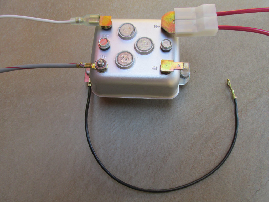
Photo courtesy of Gregory Bender.
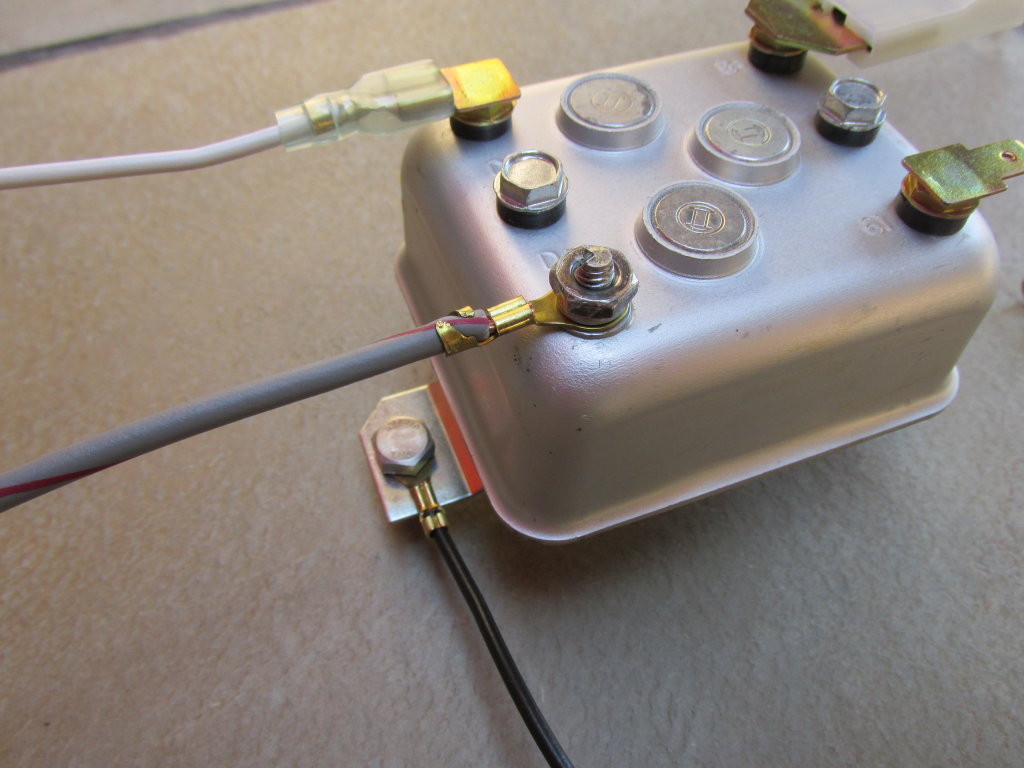
Photo courtesy of Gregory Bender.
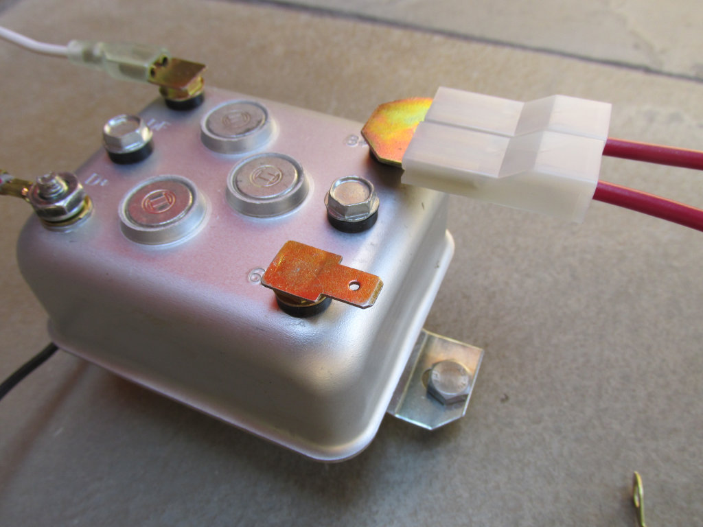
Photo courtesy of Gregory Bender.