Step 2B: Make the connections at the dash
Created:
Updated:
Make the connections at the dash
Single instrument civilian dash
- The yellow/black wire with the 4 mm male bullet terminal is plugged into the light socket for the
lights
indicator. - The white wire with the 4 mm male bullet terminal is plugged into the light socket to illuminate the speedometer.
- The white/black wire with the 4 mm male bullet terminal is plugged into the back of the speedometer.
- The brown wire with the 4 mm male bullet terminal is plugged into terminal INT on the ignition switch.
- The red wire with the 4 mm male bullet terminal is plugged into terminal 15/54 on the ignition switch.
Photo courtesy of Gregory Bender.
Photo courtesy of Gregory Bender.
Photo courtesy of Gregory Bender.
Photo courtesy of Gregory Bender.
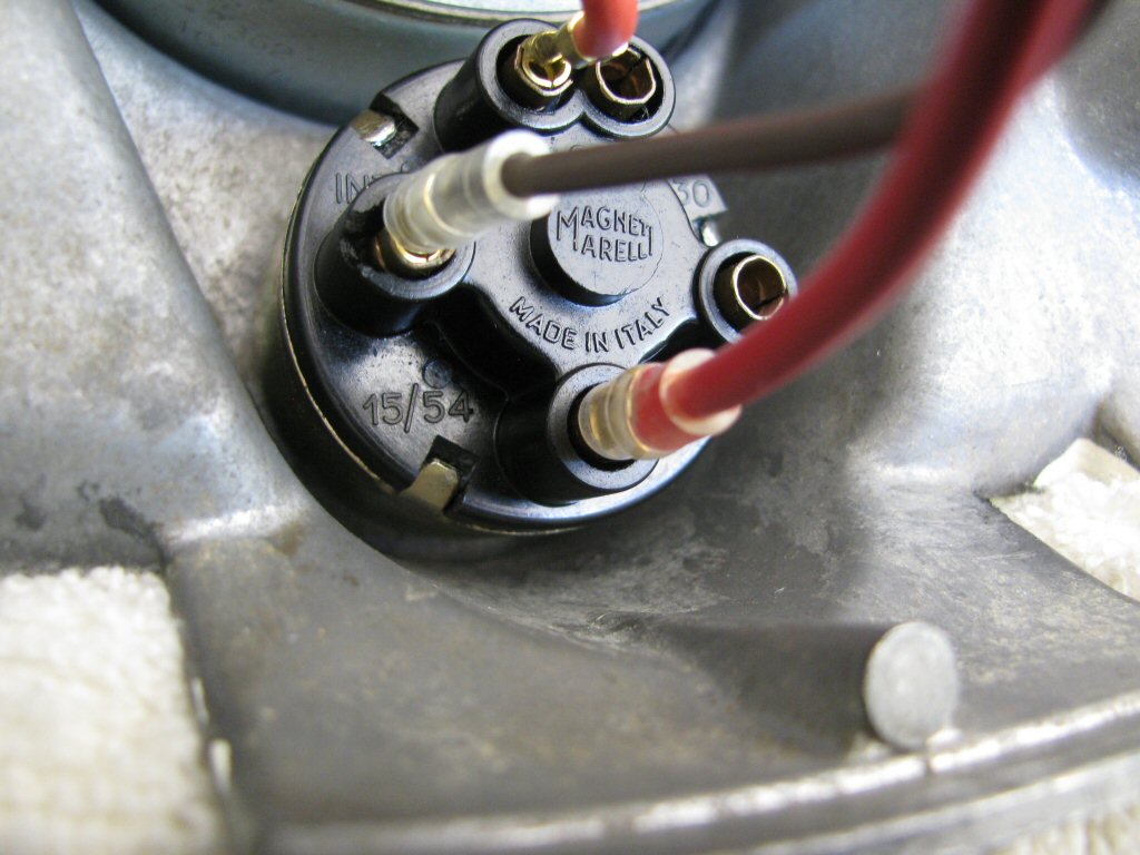
Photo courtesy of Gregory Bender.
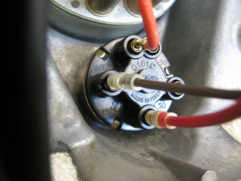
Photo courtesy of Gregory Bender.
Dual instrument civilian dash
- The yellow/black wire with the 4 mm male bullet terminal is plugged into the light socket for the
high beam
indicator. - The white wire with the 4 mm male bullet terminal is plugged into the illumination interconnect sub-harness (MG# 13761400). Each white wire with a 4 mm female bullet terminal is then connected to the light socket to illuminate the speedometer and tachometer.
- The white/black wire with the 4 mm male bullet terminal is plugged into the indicator light interconnect sub-harness (MG# 13761001). Each white/black wire with a 6.3 mm female spade terminal is then connected to the light socket for the neutral, generator, and oil pressure indicator lights. The blue wire with a 6.3 mm female spade terminal is connected to the positive terminal on the back of the tachometer.
- The brown wire with the 4 mm male bullet terminal is plugged into terminal INT on the ignition switch.
- The red wire with the 4 mm male bullet terminal is plugged into terminal 15/54 on the ignition switch.
Police dash
- The yellow/black wire with the 6.3 mm female spade terminal is plugged into the light socket for the
high beam
indicator. - The white wire with the 4 mm male bullet terminal is plugged into the light socket to illuminate the speedometer.
- The white/black wire with the 4 mm male bullet terminal is plugged into the indicator light interconnect sub-harness (MG# 13761000). Each white/black wire with a 6.3 mm female spade terminal is then connected to the light socket for the neutral, generator, and oil pressure indicator lights.
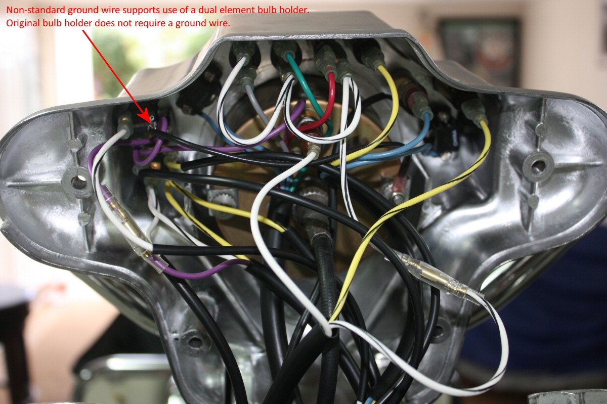
Photo courtesy of Robert Bear
Wolfe (Aloha).
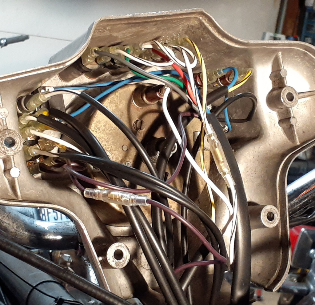
Photo courtesy of Richard Mattrass.