Step 1R: Dash connections
Created:
Updated:
Civilian V700 (single instrument dash) dash connections from the main harness
- The green wire with the 4 mm male bullet terminal is plugged into the light socket for the neutral indicator.
- The 1 mm2 red wire with the 4 mm male bullet terminal is plugged into the light socket for the generator indicator.
- The gray wire with the 4 mm male bullet terminal is plugged into the light socket for the oil pressure indicator.
- The brown wire with the 4 mm male bullet terminal is plugged into terminal 50 on the ignition switch.
- The heavier, 2.5 mm2 red wire with the 4 mm male bullet terminal is plugged into terminal 30/30 on the ignition switch.
Civilian Ambassador & Eldorado (single instrument dash) dash connections from the main harness
- The green wire with the 4 mm male bullet terminal is plugged into the light socket for the neutral indicator.
- The 1 mm2 red wire with the 4 mm male bullet terminal is plugged into the light socket for the generator indicator.
- The gray wire with the 4 mm male bullet terminal is plugged into the light socket for the oil pressure indicator.
- The heavier, 2.5 mm2 red wire with the 4 mm male bullet terminal is plugged into terminal 30/30 on the ignition switch.
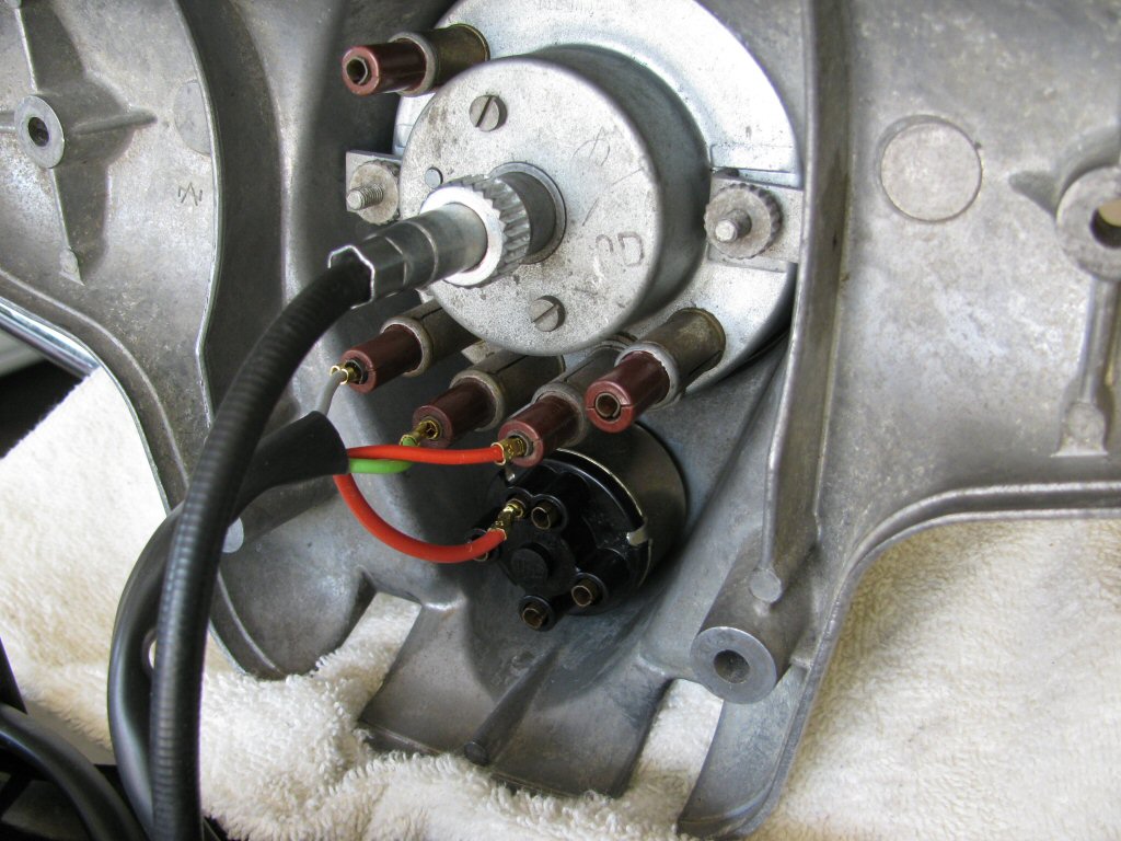
Photo courtesy of Gregory Bender.
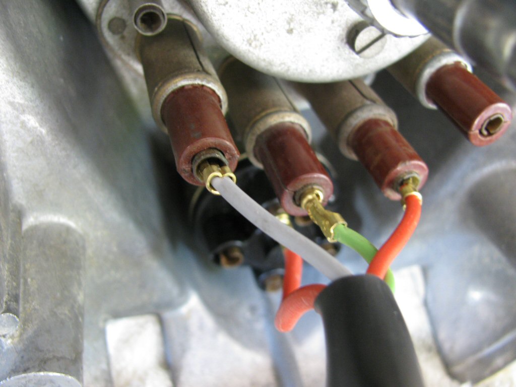
Photo courtesy of Gregory Bender.
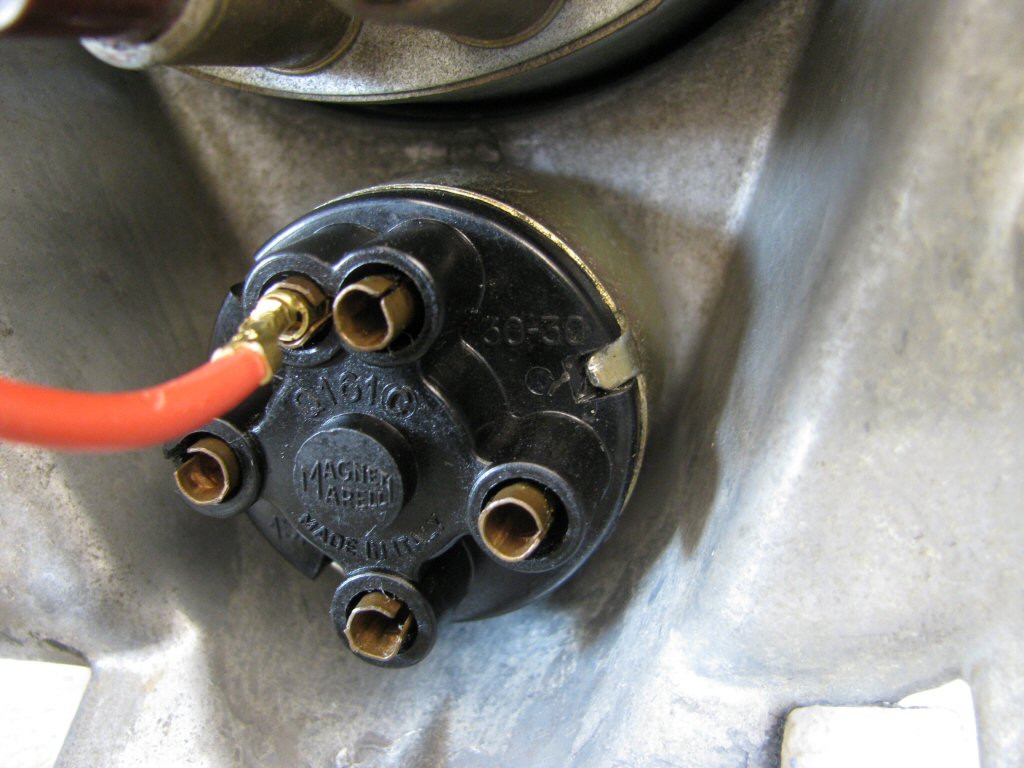
Photo courtesy of Gregory Bender.
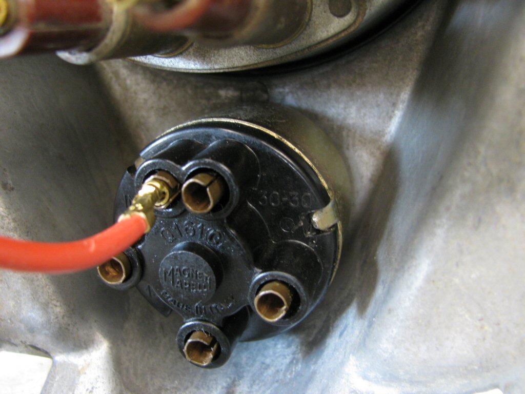
Photo courtesy of Gregory Bender.
Civilian Ambassador & Eldorado (dual instrument dash) dash connections from the main harness
- The green wire with the 4 mm male bullet terminal is plugged into the green short jumper wire for the light socket to the neutral indicator.
- The 1 mm2 red wire with the 4 mm male bullet terminal is plugged into the red short jumper wire for the light socket to the generator indicator.
- The gray wire with the 4 mm male bullet terminal is plugged into the gray short jumper wire for the light socket to the oil pressure indicator.
- The heavier, 2.5 mm2 red wire with the 4 mm male bullet terminal is plugged into terminal 30/30 on the ignition switch.
Police Ambassador & Eldorado dash connections from the main harness
- The green wire with the 6.3 mm female spade terminal is plugged into the light socket for the neutral indicator.
- The 1 mm2 red wire with the 6.3 mm female spade terminal is plugged into the light socket for the generator indicator.
- The gray wire with the 6.3 mm female spade terminal is plugged into the light socket for the oil pressure indicator.
- The two blue/black wires (with insulation stripped and wires tinned with solder) are secured with set screws to both terminals of the right push-pull switch. It does not matter which wire is secured to which set screw.
- The purple wire crimped with short jumper wires using 6.3 mm female spade terminals is plugged into the toggle switch.
Connections to the toggle switch
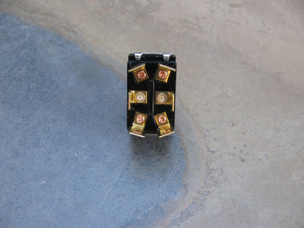
Photo courtesy of Gregory Bender.
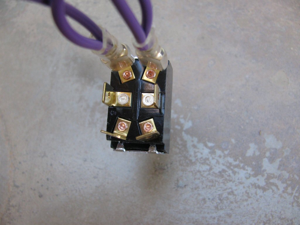
Photo courtesy of Gregory Bender.
toggle switch to 3 connection female spade connectorssub-harness are connected to the middle terminals on the toggle switch.
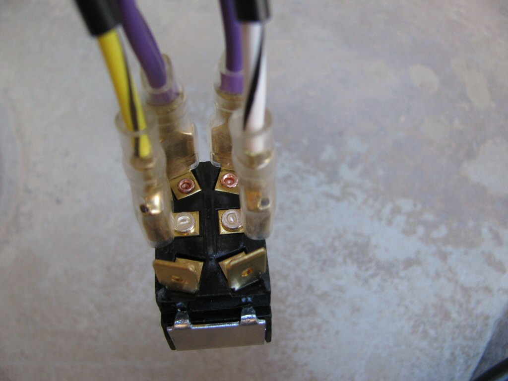
Photo courtesy of Gregory Bender.
toggle switch to 3 connection female spade connectorssub-harness are connected to the middle terminals on the toggle switch.
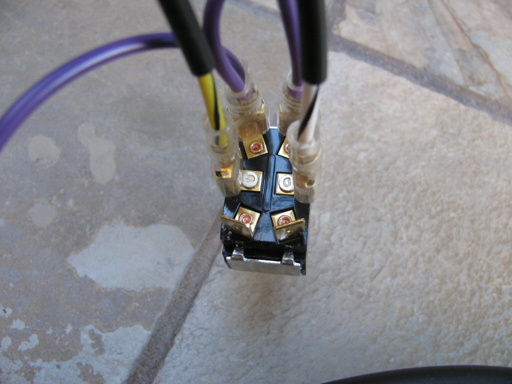
Photo courtesy of Gregory Bender.
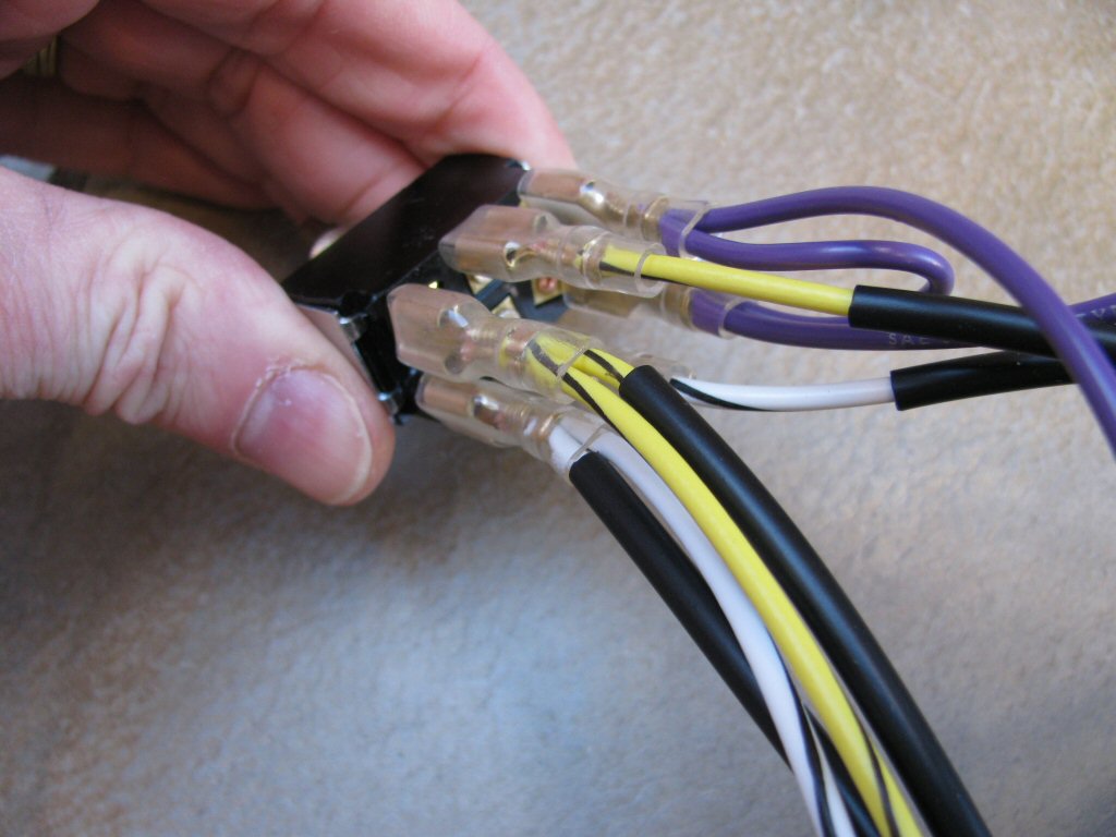
Photo courtesy of Gregory Bender.
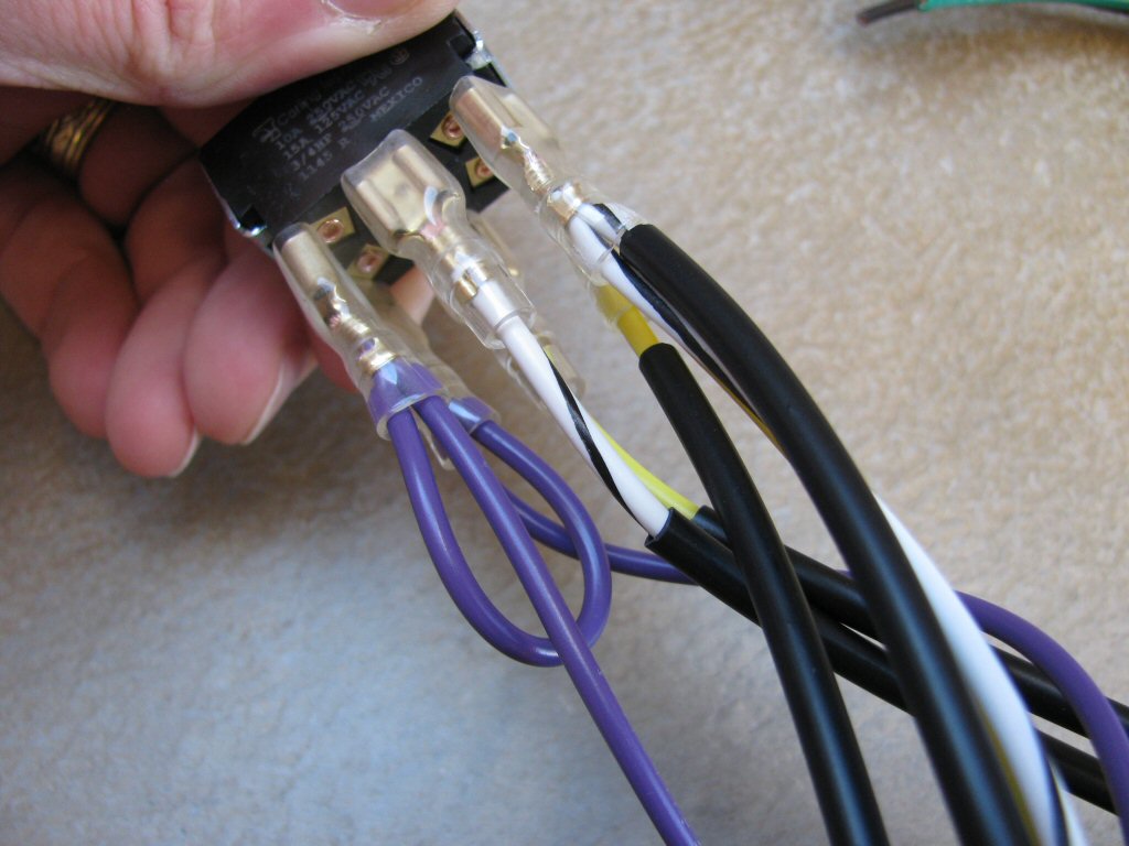
Photo courtesy of Gregory Bender.