Moto Guzzi V700, V7 Special, Ambassador, 850 GT, 850 GT California, Eldorado, and 850 California Police models
Created:
Updated:
Thanks to Gerhard Ziesemann for sending me this information via email. In Gerhard's own words and photos:
The perch thread for the cable adjuster of my 2LS front brake plate had broken (an unfortunate accident during cleaning and regreasing the brake). The idea was to reuse the plate as a rear wheel brake because I considered it extremely valuable scrap.
My inspiration was the V7 Sport rear brake. A number of details needed to be modified:
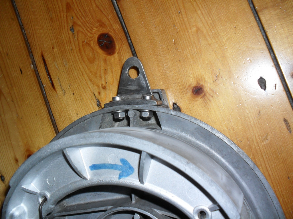
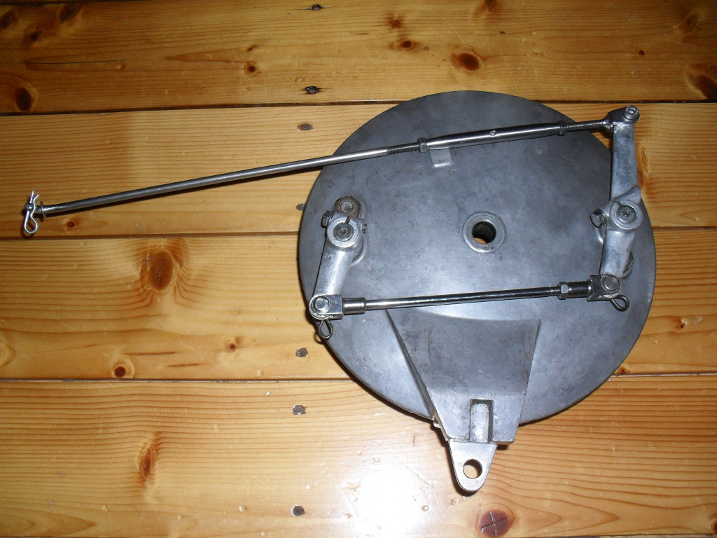
These pics show the connector point, made of 5 mm stainless steel, bent to the shape of the brake plate, the eye welded to it, and fixed with 2 Allen head screws 6 mm. The hole is 10.2 mm to hold 10 mm fasteners, so the original stay arm can still be used - it fits perfectly.
The brake plate needs a connector point to fix the stay arm.
Photo courtesy of Gerhard Ziesemann.
The brake plate needs a connector point to fix the stay arm.
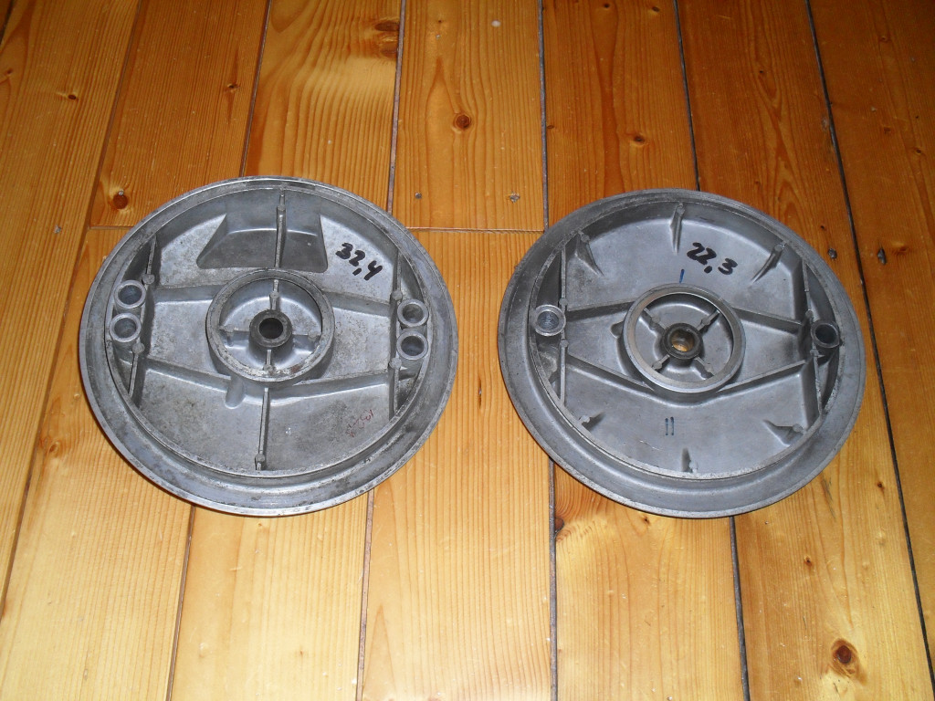
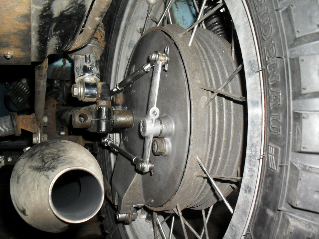
The thinner brake plate that gives room for the rear wheel hub, the diameter is ~ 65 mm.
The thickness of the brake plate needs to be reduced by approx. 10mm on the inside to the size of the rear brake plate, and the perch thread must be eliminated.
Photo courtesy of Gerhard Ziesemann.
The thickness of the brake plate needs to be reduced by approx. 10mm on the inside to the size of the rear brake plate, and the perch thread must be eliminated.
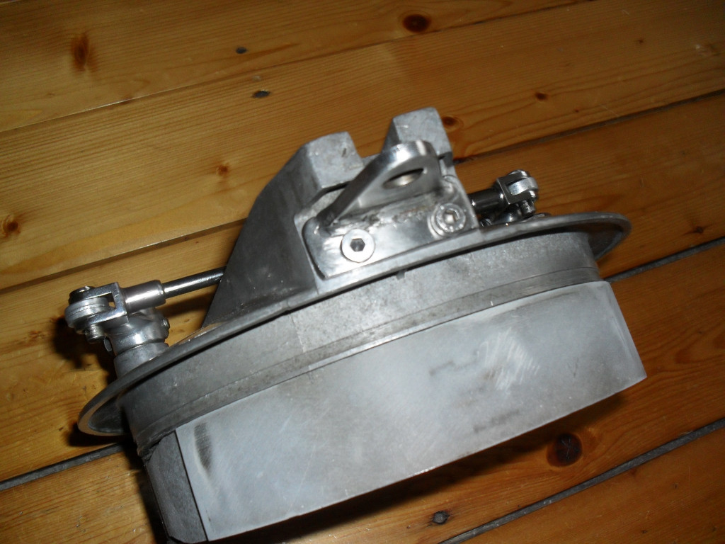
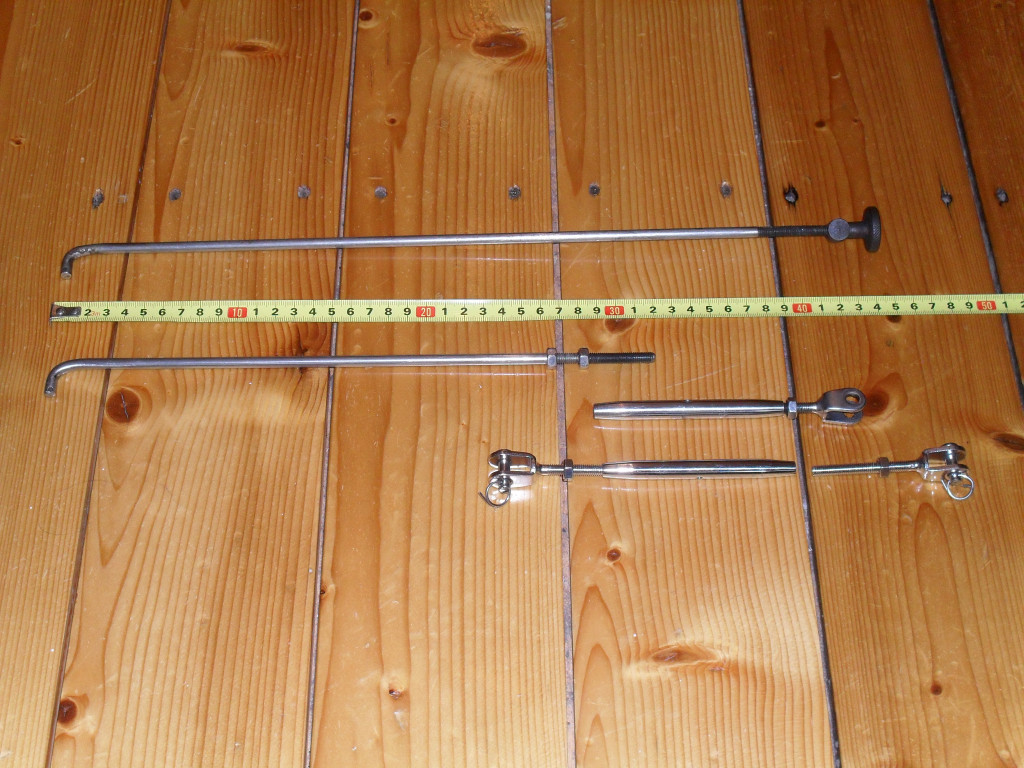
The original actuation rod (upper) and the new rod (middle) with the turnbuckle (below). The right-hand thread end is screwed to the rod while the U-type end with the left- hand thread ist mounted to the lever by a 6 mm bolt, with nuts fixing both ends. Adjustment here.
The actuation rod needs to be connected to the lever, and a turnbuckle can serve as a good adaptor if the rod is shortened. The overall length of the new rod is 315 mm (125 mm shorter than the original one), and the thread is 55 mm.
Photo courtesy of Gerhard Ziesemann.
The actuation rod needs to be connected to the lever, and a turnbuckle can serve as a good adaptor if the rod is shortened. The overall length of the new rod is 315 mm (125 mm shorter than the original one), and the thread is 55 mm.
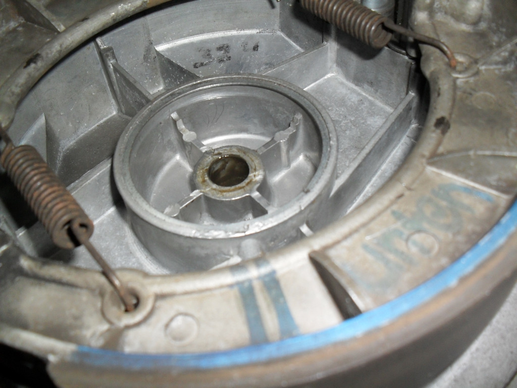
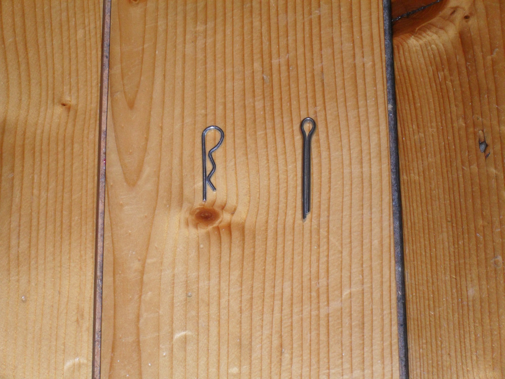
These spring cotter pins (left) are easier and faster to handle than split pins (right) to adjust the linking rod. That's why I prefer them, as you may have seen.
Photo courtesy of Gerhard Ziesemann.
These spring cotter pins (left) are easier and faster to handle than split pins (right) to adjust the linking rod. That's why I prefer them, as you may have seen.