Tightening valve head nuts and setting valve clearances
Moto Guzzi V700, V7 Special, Ambassador, 850 GT, 850 GT California, Eldorado, and 850 California Police models
Created:
Updated:
Jake Rivera sent me his explanation of how to tighten the cylinder head nuts and how to set the valve clearances. In Jake's own words:
Here are my notes for tightening up the head nuts. I know it's basic stuff but if you're a novice (like me) it may be helpful. Feel free to use them or not, make corrections, whatever you want. I'm happy to be a ghost contributor. Just glad to have your site available to me -...trying to give back.
Loose head nuts and/or improper valve clearances can effect engine performance. My bike had wildly inconsistent timing between cold and hot running temperatures. Charlie Mullendore with Antietam Classic Cycle tightened up my head bolts and the problem was gone. However, after 750 miles I had to retighten the head nuts. The aim here is to torque the head nuts to spec, inspect the push rods, and set the valve clearances to spec.
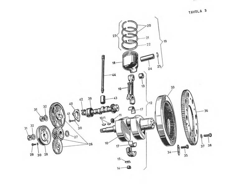
The camshaft, which resides over top the crankshaft, makes the valves go up and down. The crankshaft makes the pistons go up and down. The generator pulley is attached to the crankshaft. The crankshaft rotates 2× for every 1× turn of the camshaft. This is important for locating the compression stroke of the cycle. You will use a 26 mm socket placed on the front pulley nut to turn the engine clockwise to the top dead center of the compression stroke for each cylinder.
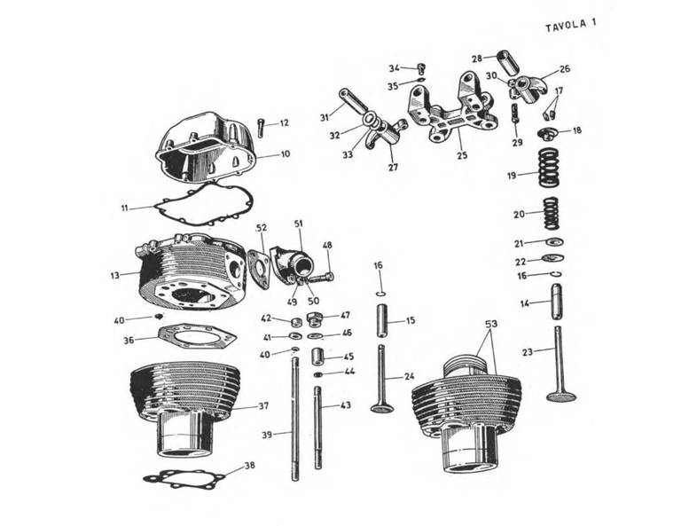
Remove the rocker arm by removing rocker spindle bolt and pushing the spindle out.
Remove the pushrods and inspect. Check for signs of wear.
Using a torque wrench, tighten the 6 head bolts to spec (29 - 32 lbs ft). There are four bolts holding the rocker arm. The two remaining head bolts are located under the cover nut over top the rocker arm, and one down low by the spark plug. The head bolt under the cover nut is a #10 Allen head bolt. An extension will be needed to access the one down by the spark plug. Use the extension on your torque wrench for all the bolts to ensure even tightening.
Install the pushrods making sure they are seated correctly.
Install the Rocker arm and spindle.
Setting the Valve Clearances:
To set the valve clearances we want the piston to be at top dead center of the compression stroke. Remember, you have to turn the pulley wheel two times for one complete cycle of the engine. Here's the engine cycle sequence:
Intake valve opens
Intake valve closes
Piston up (compression)
Piston down
Exhaust valve opens
Exhaust valve closes
Rotating the engine clockwise, I use a long Allen wrench that I mark to locate the top of the piston stroke. You can use your finger over the spark plug hole as you rotate the engine to feel that you are on the compression stroke.