Shocks - Tear down and rebuild of the stock shock step 2: inner
Moto Guzzi V700, V7 Special, Ambassador, 850 GT, 850 GT California, Eldorado, and 850 California Police models
Updated:
// //
The following procedure is applicable to the commonly fitted original equipment rear shocks.
I extracted this information from Rob Prins on the old Yahoo! Loopframe_Guzzi news group (which has now moved to Groups.io). In Rob's own words:
No one should accept responsibility for the accuracy of this document since I wrote it myself and I could be wrong.
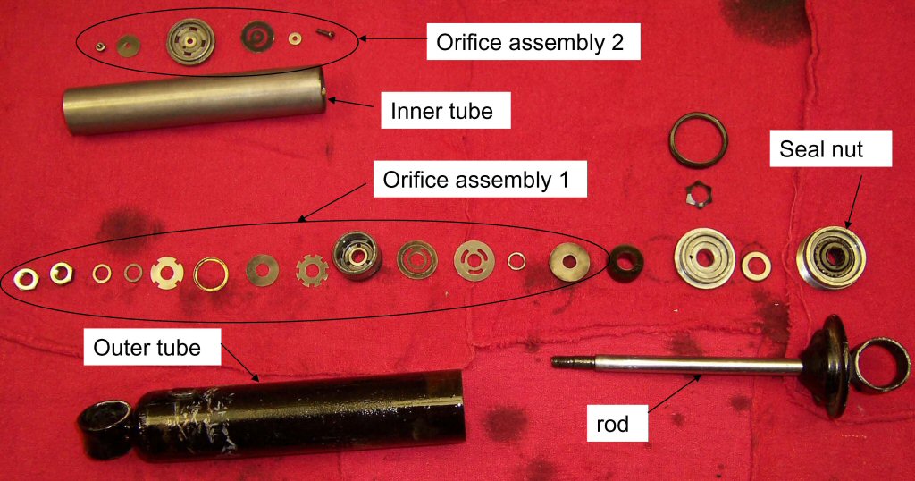
Main parts are (my names): outer tube, inner (pressure) tube, rod, seal nut, orifice assembly #1, orifice assembly #2
The seal nut must be removed using a pin wrench, I used a bicycle tool I have in my stock, but I may build something custom for future use.
Photo courtesy of Rob Prins.
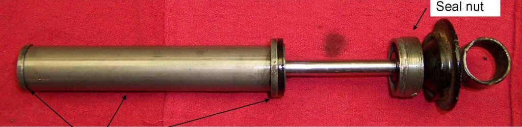
After the seal nut is backed out of the outer tube, the inner assembly can be removed; here is what she looks like.
These parts, (left to right: orifice assembly #2, inner tube, orifice assembly #1) are not attached to each other. I think they are pushed together by the seal nut when installed, but they easily fall apart in disassembly
Photo courtesy of Rob Prins.
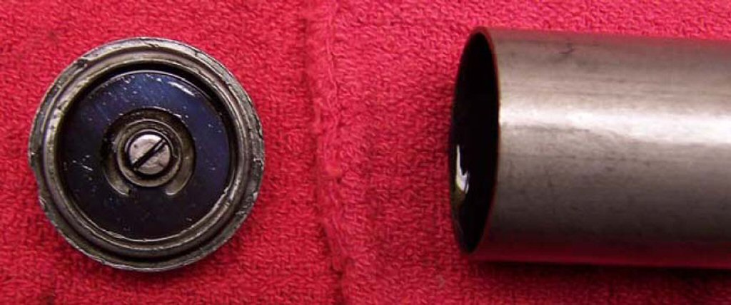
Orifice assembly #2 basically falls off of the inner tube
Photo courtesy of Rob Prins.
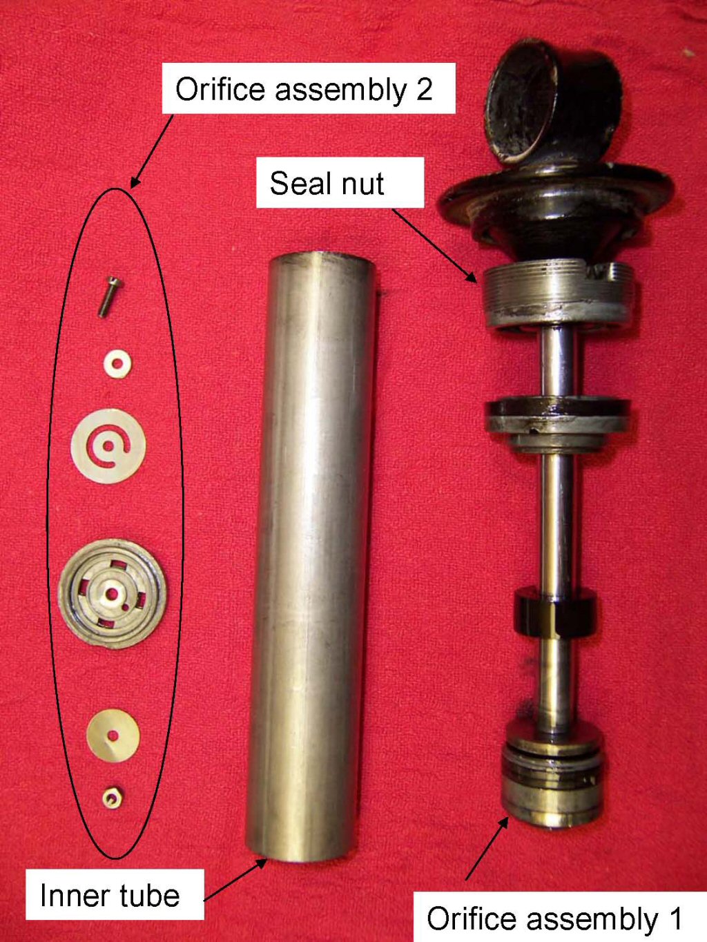
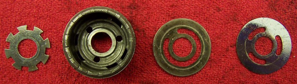
From right to left, the rod assembly including seal nut and orifice assembly #1, the inner tube, and orifice assembly #2 (disassembled).
As the shock extends and compresses as with normal driving, orifice assembly #1 is forced up and down in the oil that is in the inner tube.
Since you can't really compress the volume of oil, it has to go somewhere, in this case it is forced to flow through the orifice assemblies.
Flow resistance is related to orifice size, oil viscosity, and oil speed. As you might expect, resistance increases as either the orifice size is decreased, the viscosity is increased, or the velocity is increased.
Photo courtesy of Rob Prins.
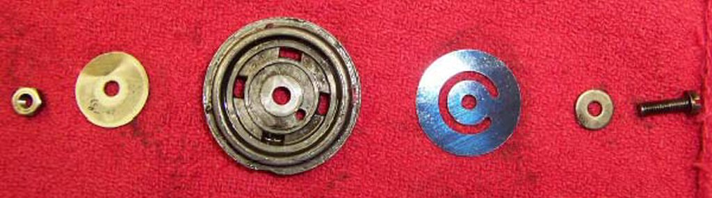
Orifice assembly #2 has 3 basic parts; the orifice plate (center) and two thin disks on either side that act as reed valves. The remaining hardware clamps the 3 basic parts together. The orifice plate has 6 holes, the center hole is for the clamping bolt, the remaining 5 holes are for oil to pass through.
As the shock is compressed, oil is forced against the disk plate shown on the right. The disk plate acts as a reed valve and closes off the 4 rectangular holes, but the C shaped slot allows the oil to go through the small hole that is positioned at roughly 4 o'clock relative to the clamp hole. Apparently oil goes through this hole with significant force since the small disk (shown on the left) is bent; both shocks I took apart showed this effect.
Photo courtesy of Rob Prins.
Orifice assembly #1 is mounted to the rod and has more parts than orifice assembly #2 (not all of them are shown in the picture) but the operation is basically the same.
The different orifice sizes and the reed valves are (presumably) the result of the original designer specifying different damping ratios for compression and rebound.
Photo courtesy of Rob Prins.
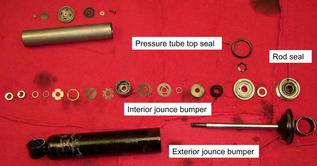
There are 4 rubber parts in the assembly, one of which is visible without disassembly. My names for the parts are: exterior jounce bumper, interior jounce bumper, rod seal, and pressure tube top seal. All of them were in decent shape in my case, which is good because I have no idea where to get new ones.
Photo courtesy of Rob Prins.
What I did was:
Clean all the (non-rubber) parts with mineral spirits
Replace oil with SAE 30 (this may prove to be too stiff)
I attempted to measure how much oil was in the shock when I disassembled it. However, before I took them apart I noticed a dead-band on rebound where after compressing the shock I could rebound it without much resistance for a short distance - not enough oil in the pressure tube? I filled the shock on reassembly; as I turned the seal nut back into the outer tube the extra oil was forced past the threads so it self-leveled.
What could be done:
You could tune the parts by changing hole sizes etc but if you want real tune-ability you should pony up and get Ikons. A better approach for the budget minded would be to tune with viscosity, find one you like and stick with it.
I didn't do anything special to seal the threads on the seal nut. This may be a problem, but I'm not convinced it will be since the oil is only pressurized when it is in the inner pressure tube.
I may yet attempt to measure the damping ratio of an original unit and compare it to rebuilt units containing different viscosity oils. I think I can do this by applying a load (like a dumbbell) and seeing how long it takes the load to extend or compress the shock. I guess I could get denser data by testing with various loads. If I get carried away I could test my Ikons the same way for each dial setting as a comparison.