Moto Guzzi V700, V7 Special, Ambassador, 850 GT, 850 GT California, Eldorado, and 850 California Police models
Created:
Updated:
// //
Disassembling the distributor
The complete distributor, removed from the engine case.
Photo courtesy of Gregory Bender.
Remove the distributor cap.
Photo courtesy of Gregory Bender.
Remove the rotor.
Photo courtesy of Gregory Bender.
Remove the bolt that secures the body of the distributor to the distributor base.
Photo courtesy of Gregory Bender.
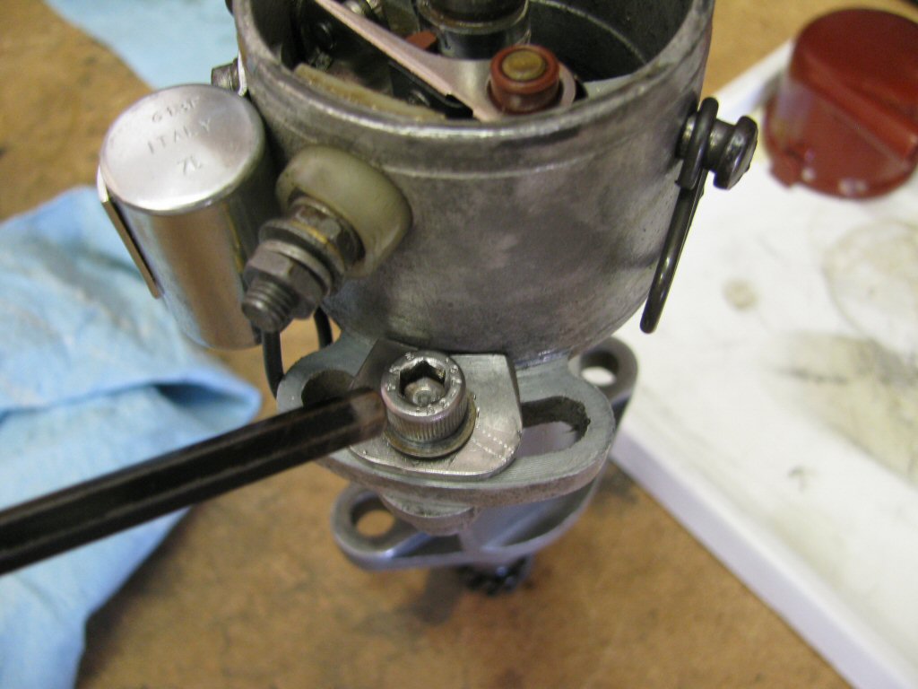
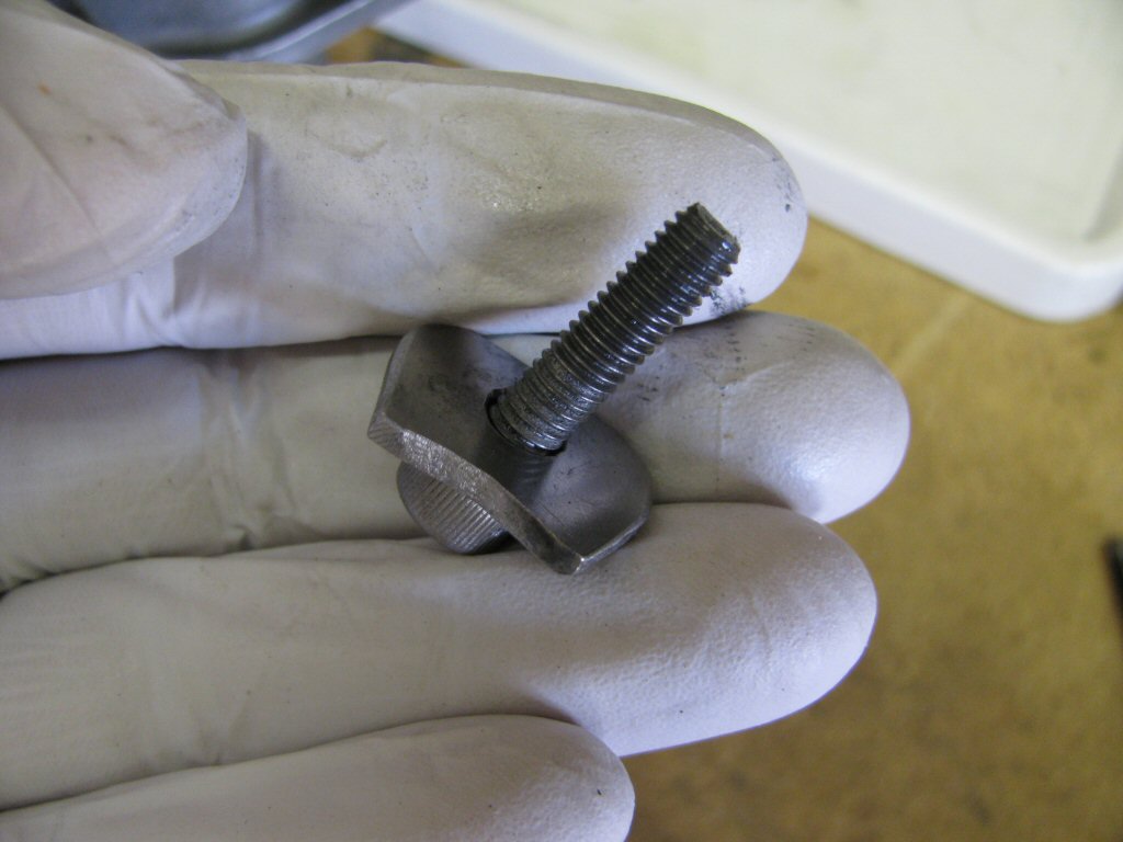
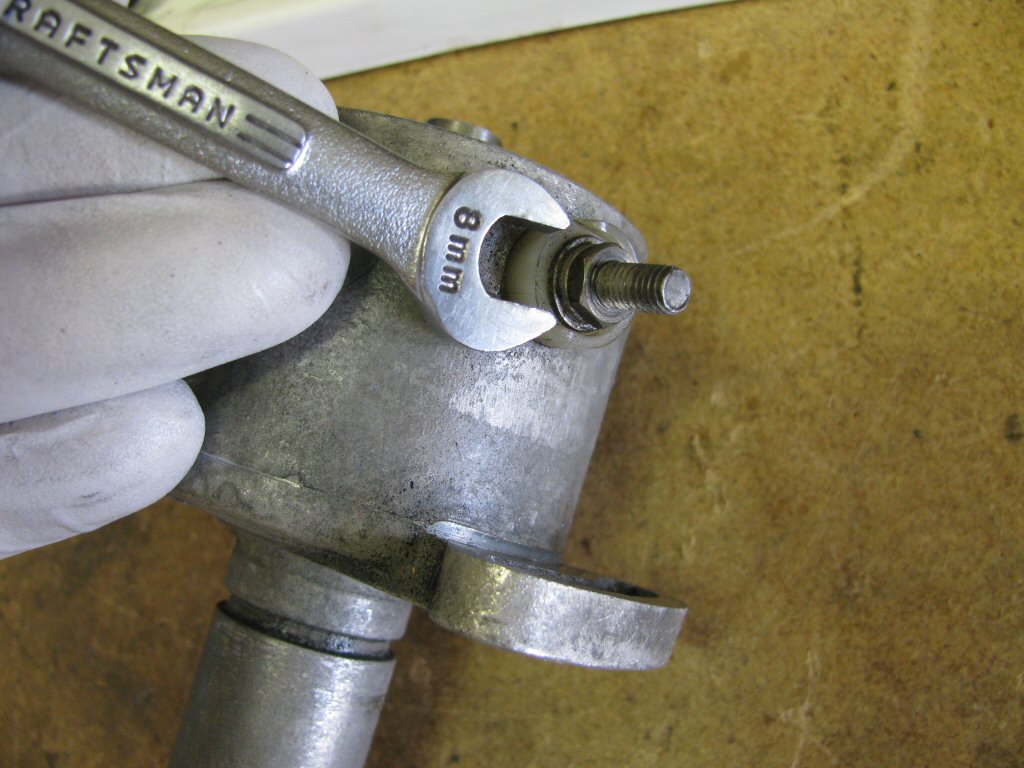
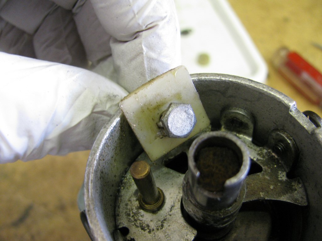
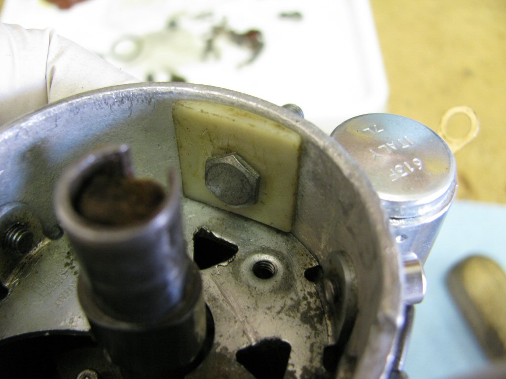
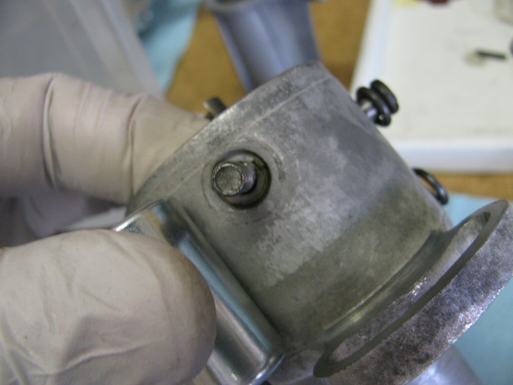
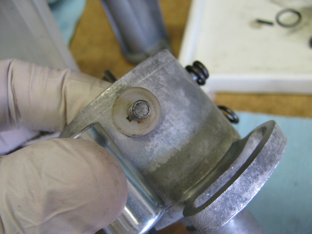
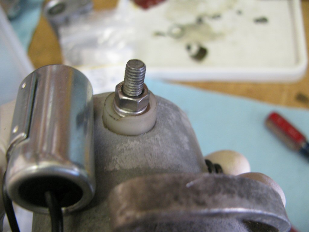
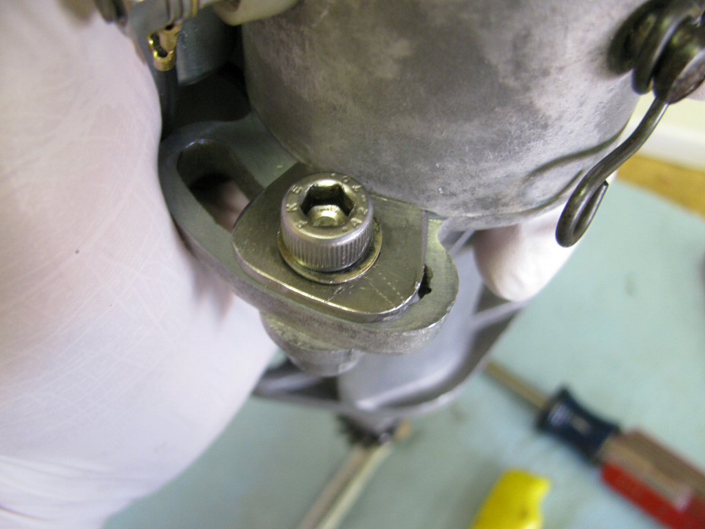
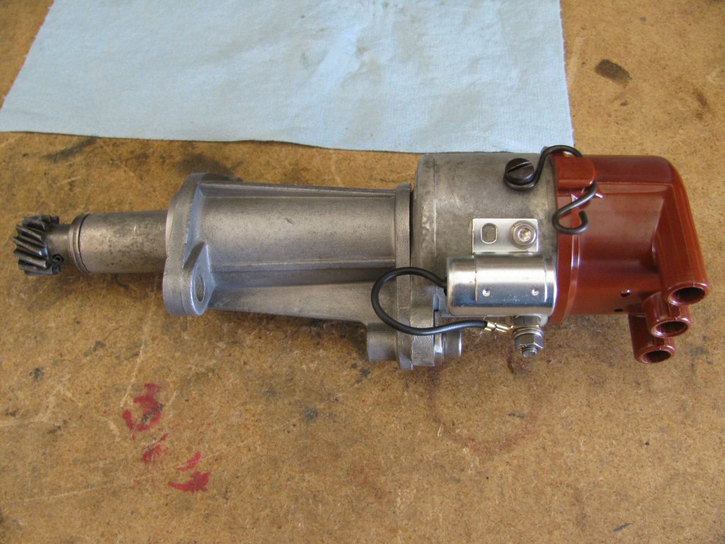
This distributor has had a special washer fabricated to spread out the tightening force and prevent indentation into the softer aluminum of the distributor body. Nice.
Photo courtesy of Gregory Bender.
Slide the distributor base off of the distributor body.
Photo courtesy of Gregory Bender.
The distributor body with the base completely removed.
Photo courtesy of Gregory Bender.
Remove this o-ring.
Photo courtesy of Gregory Bender.
To expose this groove.
Photo courtesy of Gregory Bender.
Remove the nut that secures the wire terminal from the condenser.
Photo courtesy of Gregory Bender.
Remove the screw that secures the condenser to the distributor body.
Photo courtesy of Gregory Bender.
Remove the screw that secures the points in place.
Photo courtesy of Gregory Bender.
Remove the nut that secures the metal strap from the points.
Photo courtesy of Gregory Bender.
Remove the plastic insulator from the outside.
Photo courtesy of Gregory Bender.
Remove the points (both pieces).
Photo courtesy of Gregory Bender.
Remove the bolt from the inside along with the plastic insulator.
Photo courtesy of Gregory Bender.
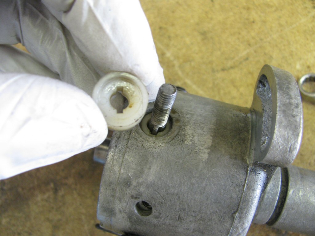
Note that the hole in the plastic insulator is not centered (top to bottom). The hole is closer to the bottom. If you flip it around, it will not fit properly. Also note that the bolt is shaped such that it will fit the insulator in a keyed fashion.
Photo courtesy of Gregory Bender.
Remove the shoulder bolt and the spring clip that holds the distributor cap in place.
Photo courtesy of Gregory Bender.
Just another photo of the other shoulder bolt and spring clip.
Photo courtesy of Gregory Bender.
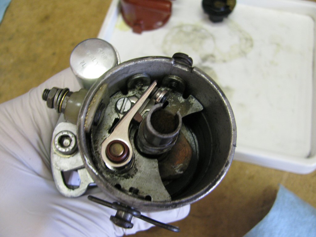
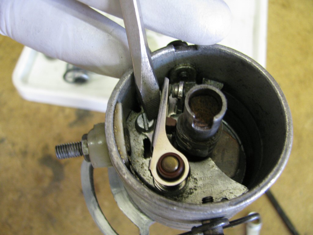
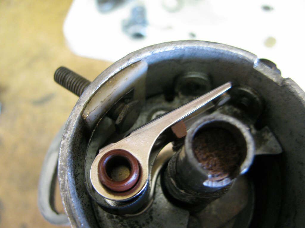
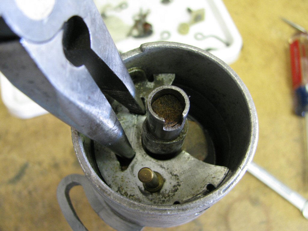
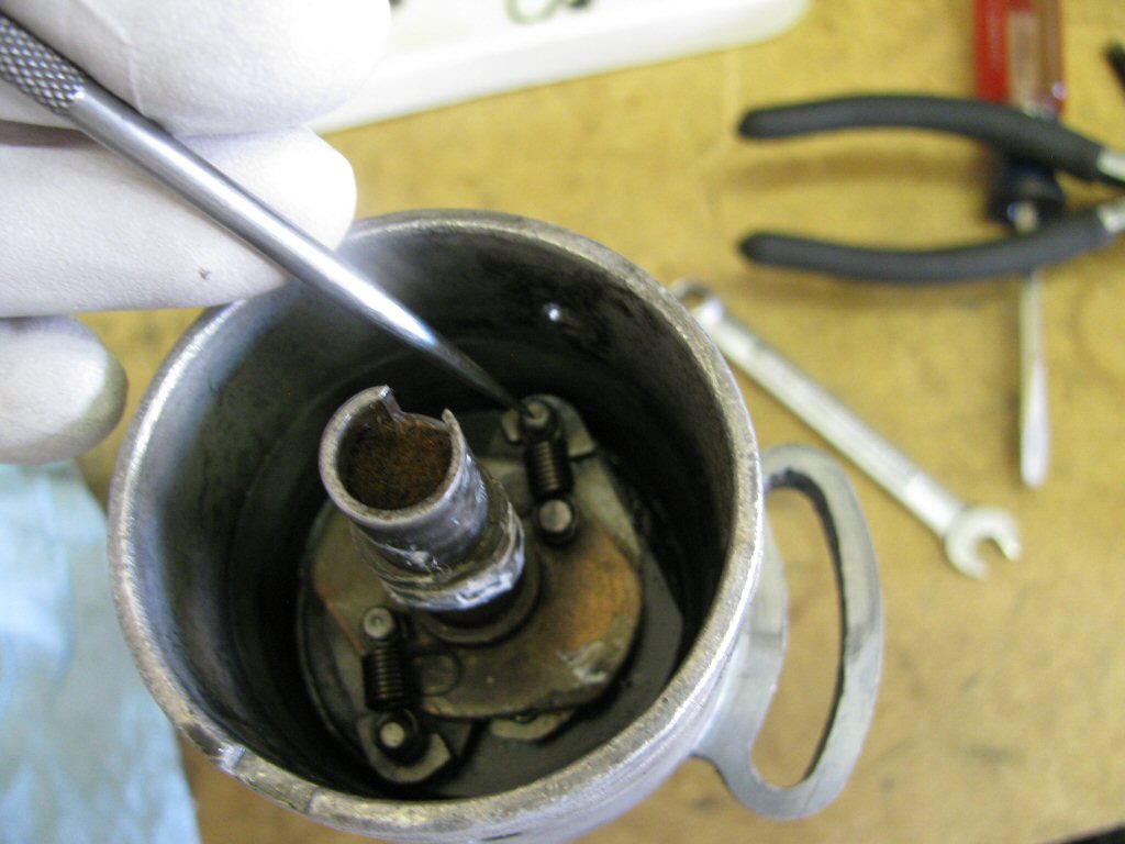
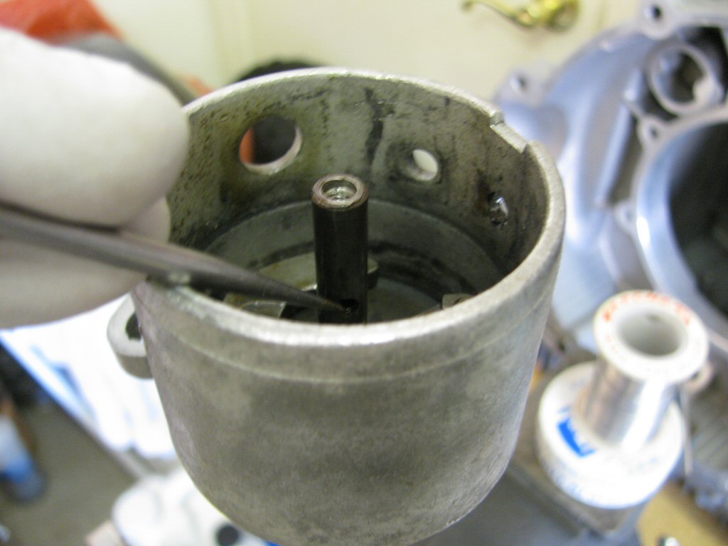
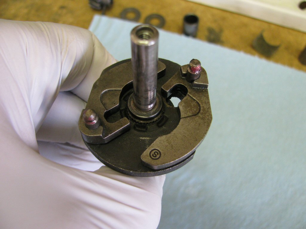
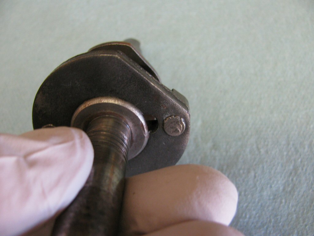
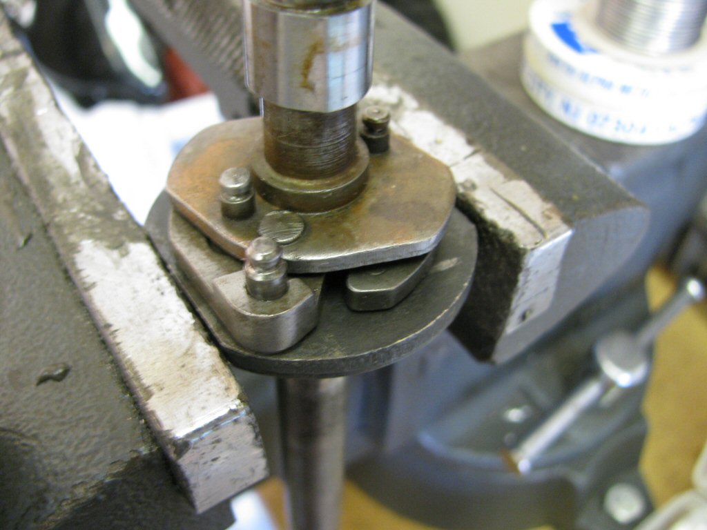
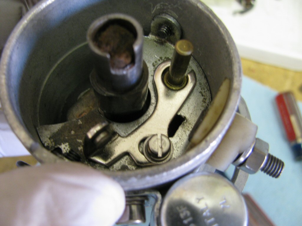
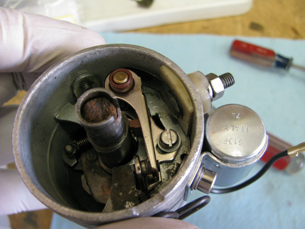
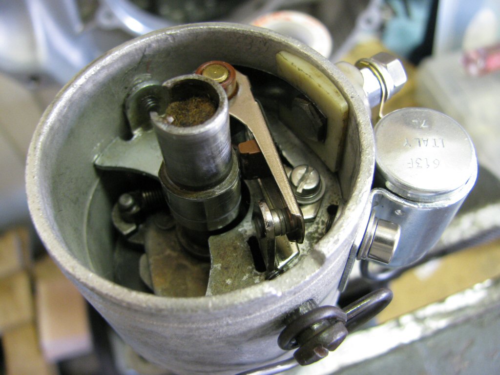
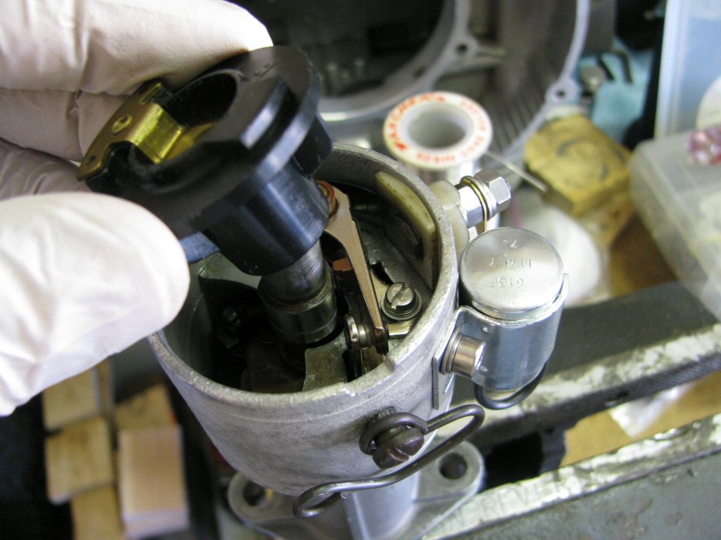
Using a needle nosed pliers, remove the plate as shown. DO NOT GRAB THE POST ON WHICH THE POINTS PIVOT! Doing so will scar the pivot and the points will not pivot smoothly. Wiggle it back and forth until the plate is free.
Photo courtesy of Gregory Bender.
Here is what it looks like with the plate removed.
Photo courtesy of Gregory Bender.
Here is one advance spring.
Photo courtesy of Gregory Bender.
Remove the advance spring.
Photo courtesy of Gregory Bender.
Here is the other advance spring.
Photo courtesy of Gregory Bender.
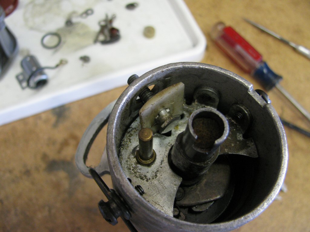
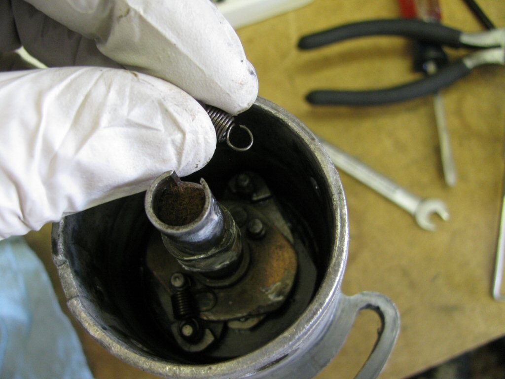
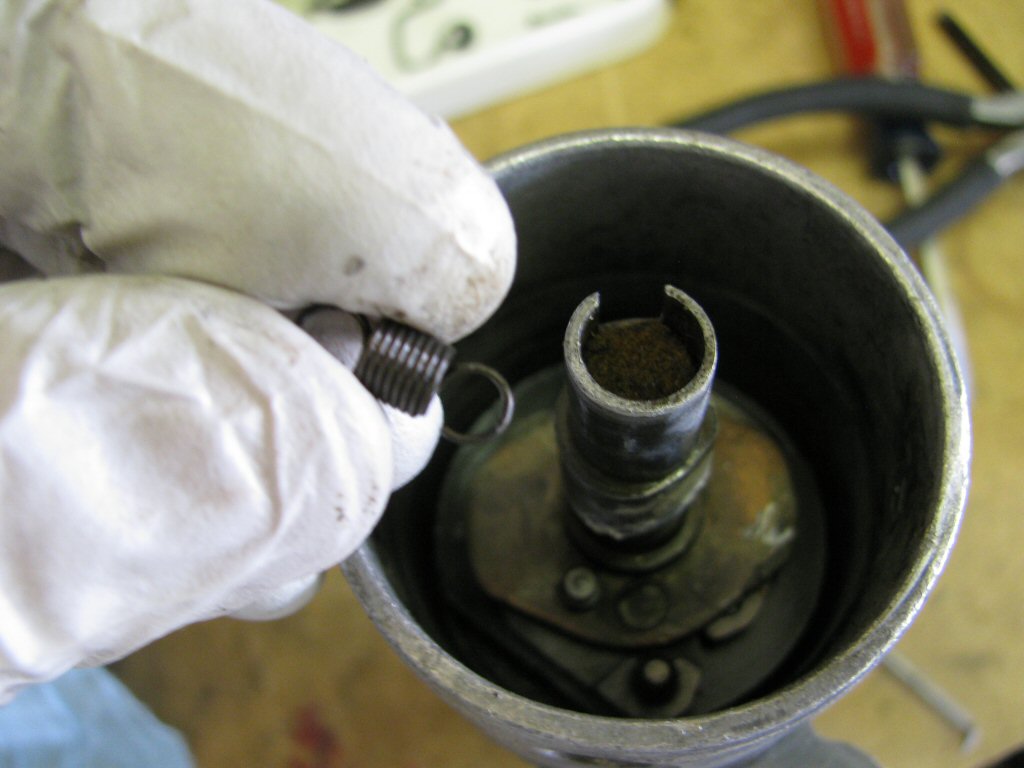
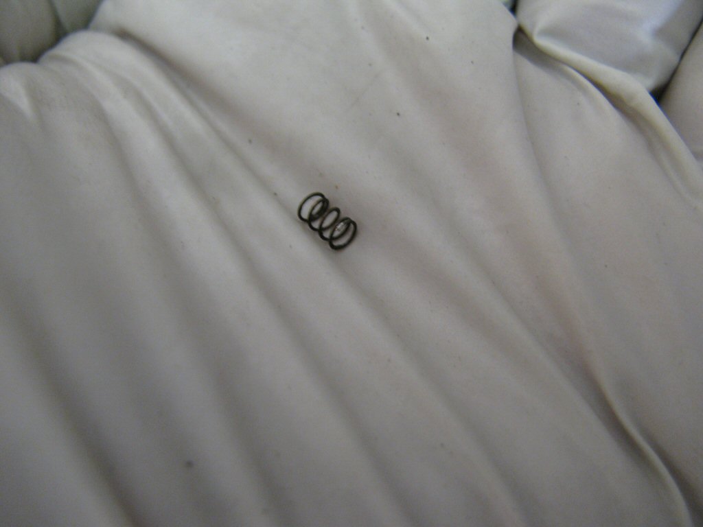
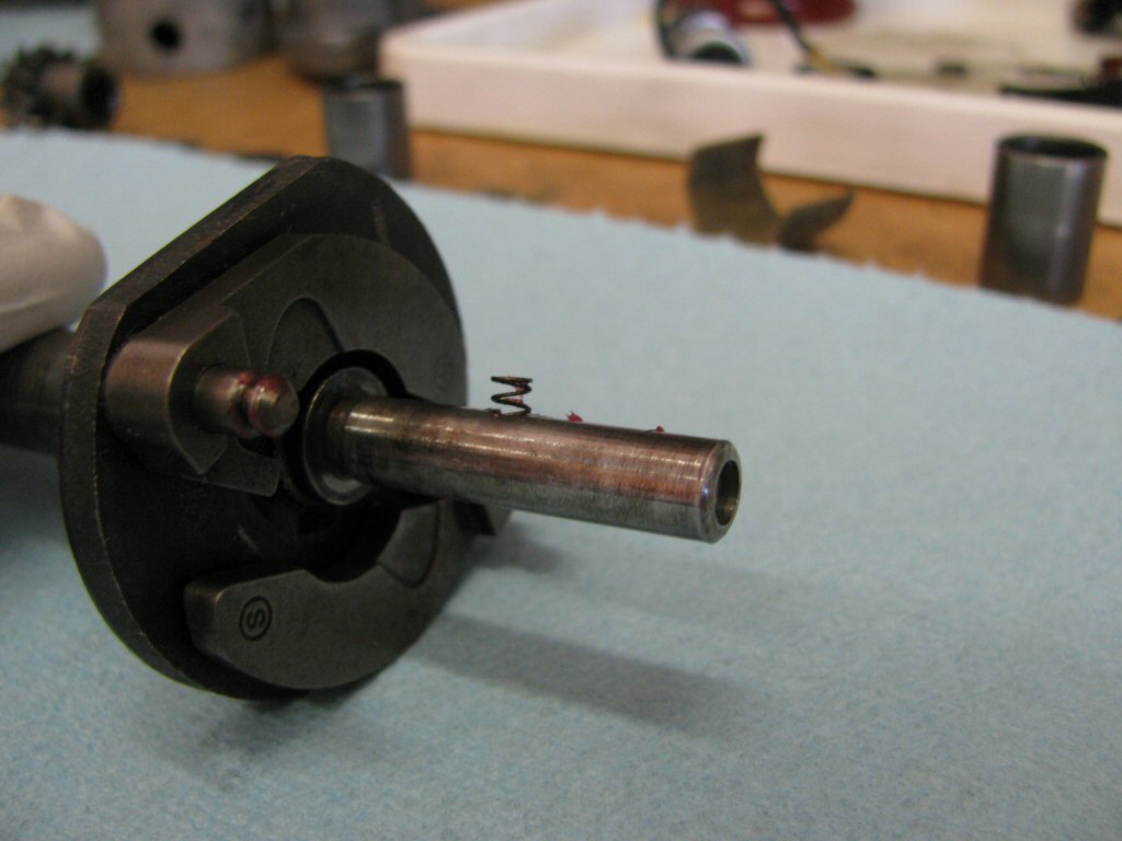
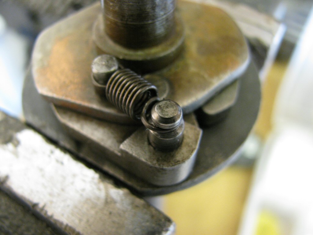
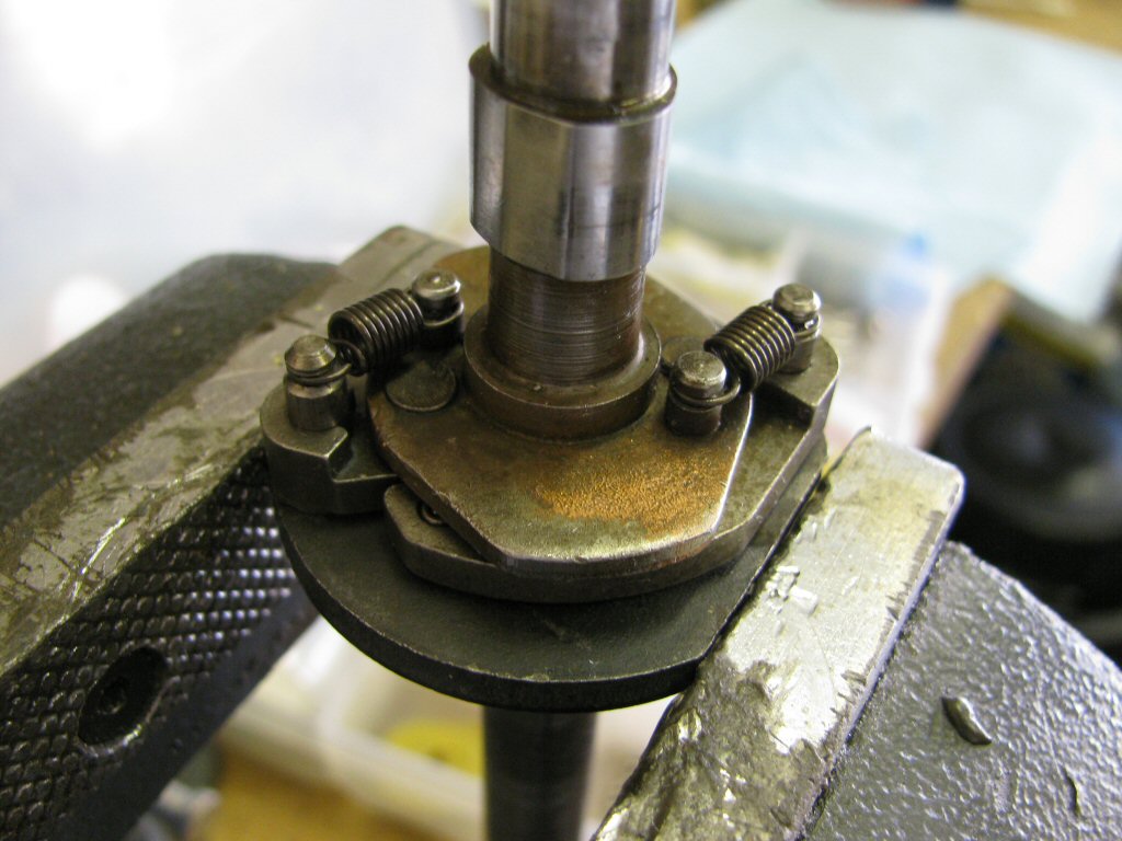
Remove it. Please note that this distributor was set up to use two of the shorter, eight coil advance springs. Mark Etheridge of Moto Guzzi Classics likes this modification. From the factory, one shorter eight coil spring and one longer nine coil spring were used.
Photo courtesy of Gregory Bender.
Here is the little felt plug that covers a screw.
Photo courtesy of Gregory Bender.
Remove the little felt plug.
Photo courtesy of Gregory Bender.
Secure the bottom gear in a vice. Protect the gears with blocks of wood or similar.
Photo courtesy of Gregory Bender.
Remove the screw that was exposed when you removed the little felt plug.
Photo courtesy of Gregory Bender.
Here is the removed screw.
Photo courtesy of Gregory Bender.
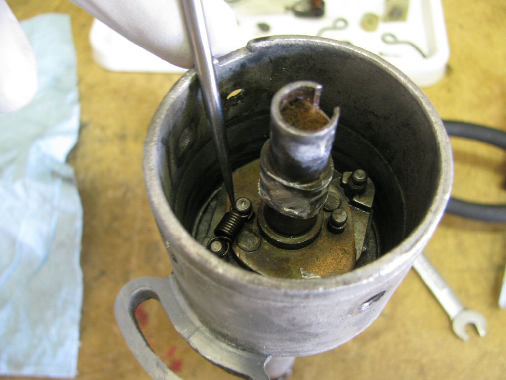
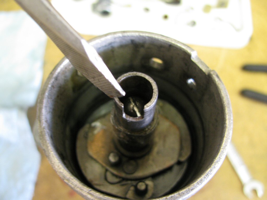
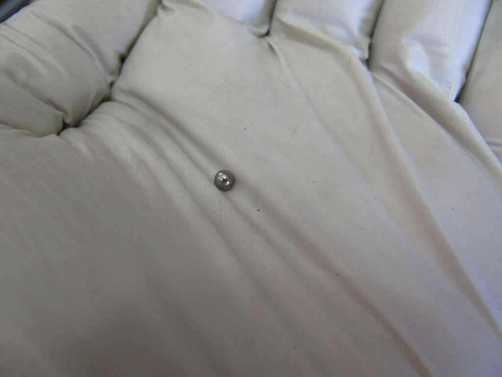
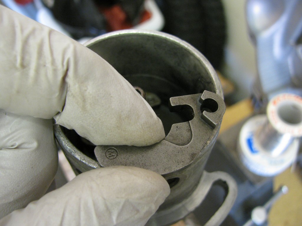
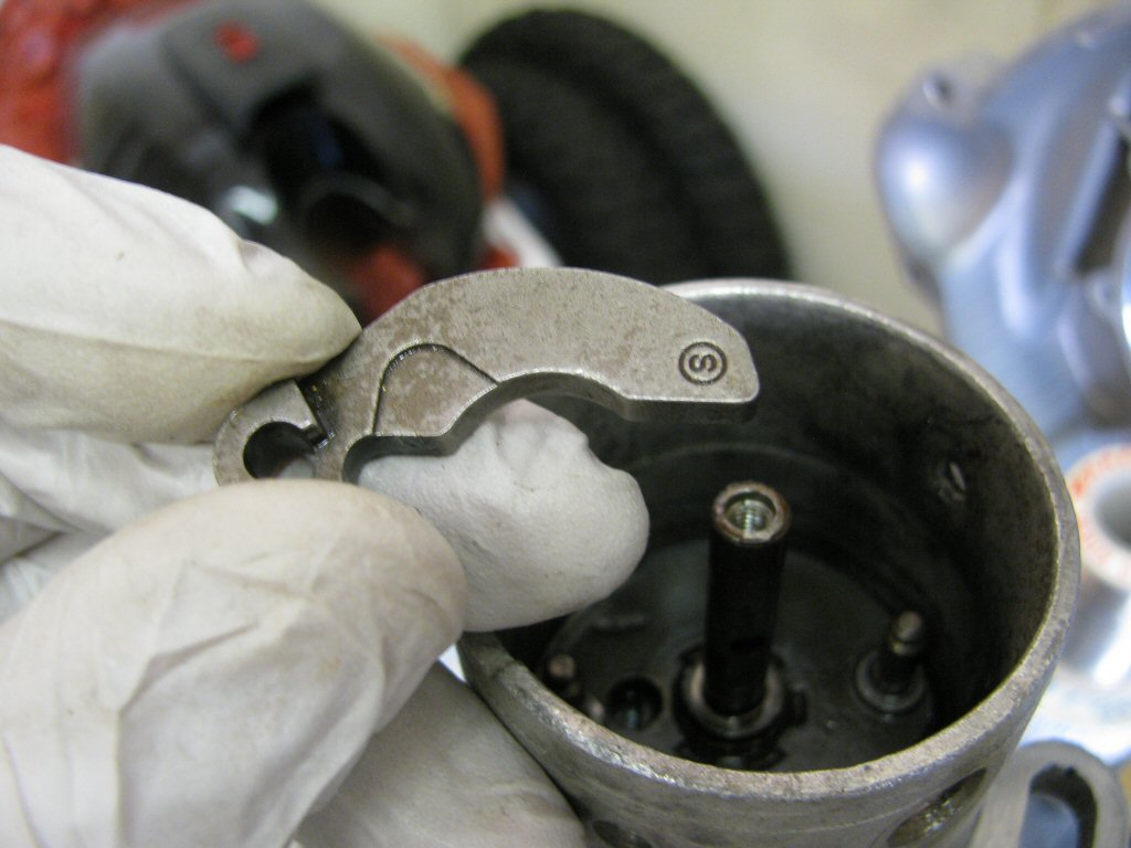
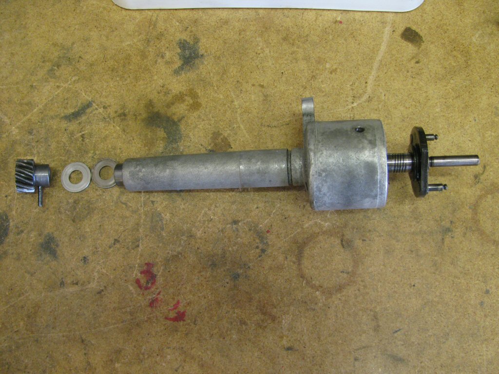
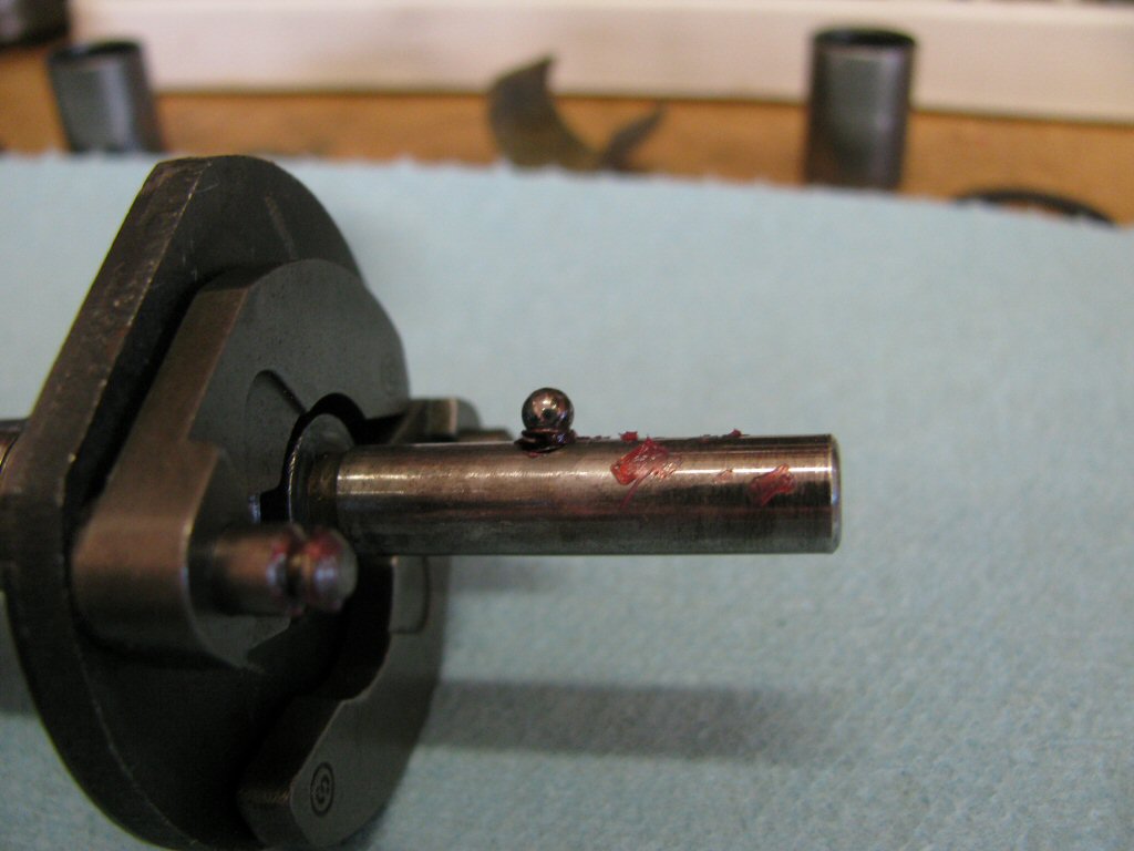
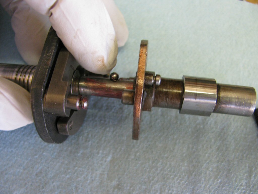
Remove the advance mechanism. When you pull it up, a small ball bearing and the spring behind the ball bearing will fall out. Be careful not to loose these tiny pieces.
Photo courtesy of Gregory Bender.
Here is the tiny ball bearing.
Photo courtesy of Gregory Bender.
The spring remained in the hole.
Photo courtesy of Gregory Bender.
Here is the tiny spring.
Photo courtesy of Gregory Bender.
Remove one advance weight.
Photo courtesy of Gregory Bender.
Remove the other advance weight.
Photo courtesy of Gregory Bender.
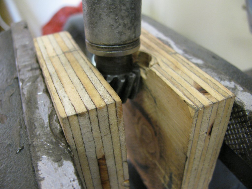
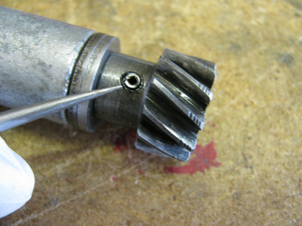
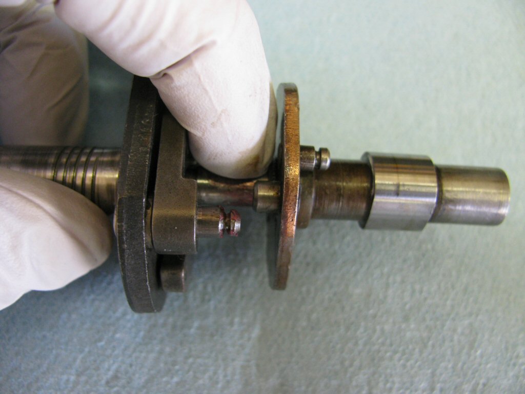
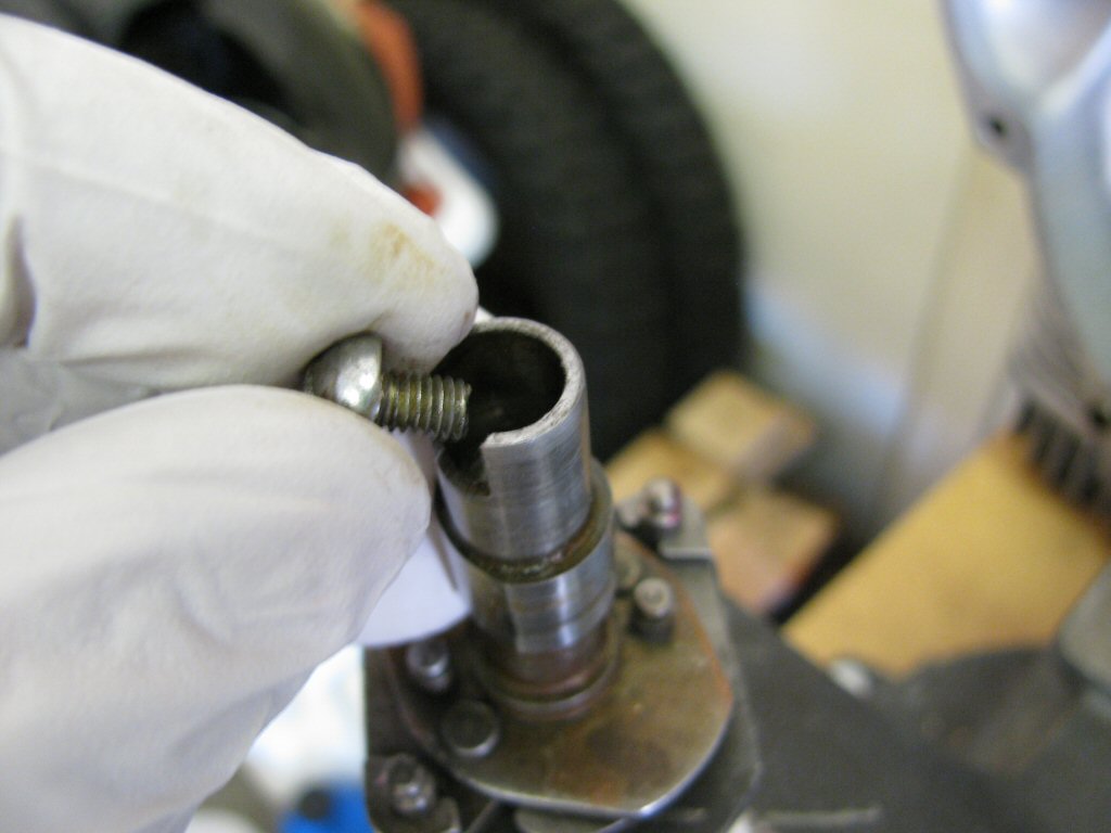
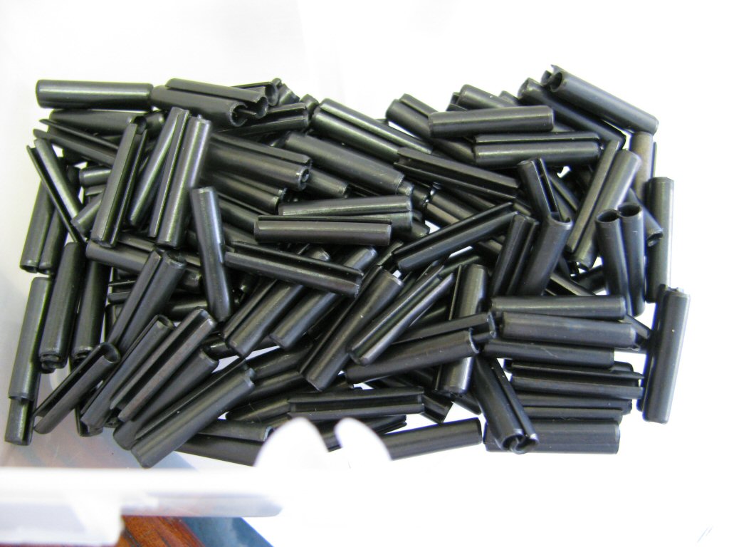
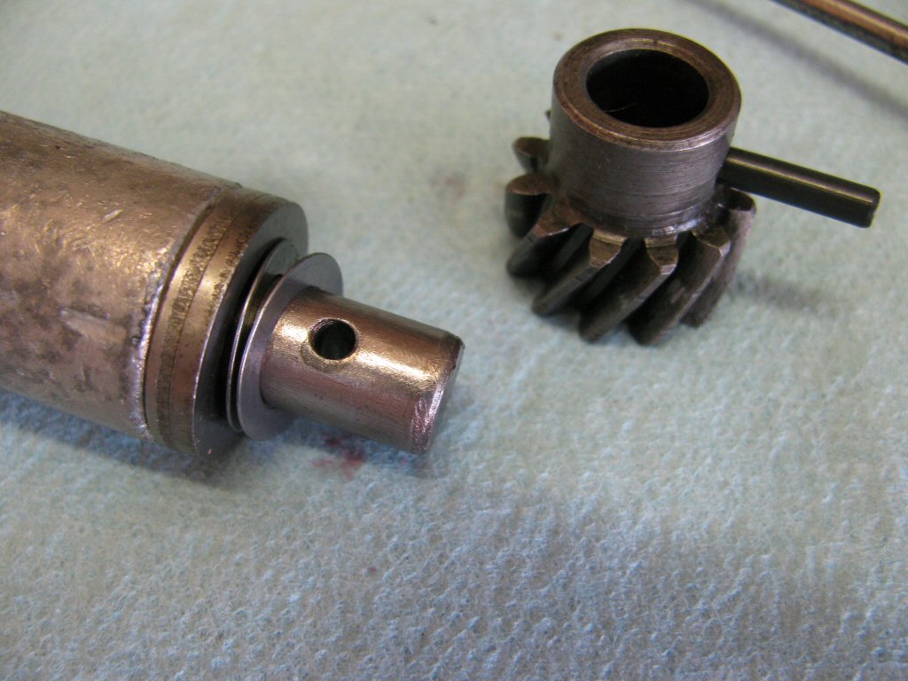
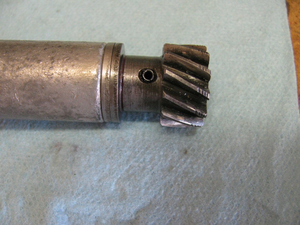
Remove the pin that secures the gear to the shaft. From the factory, this pin is solid and peened at both ends. This roll pin was replaced during a previous rebuild. Comparatively speaking, roll pins are very easily removed. The solid pins can be difficult. Please reference the techniques elsewhere on this page for guidance on removing the solid pin.
Photo courtesy of Gregory Bender.
Here is the roll pin driven most of the way out.
Photo courtesy of Gregory Bender.
The drive gear can be removed.
Photo courtesy of Gregory Bender.
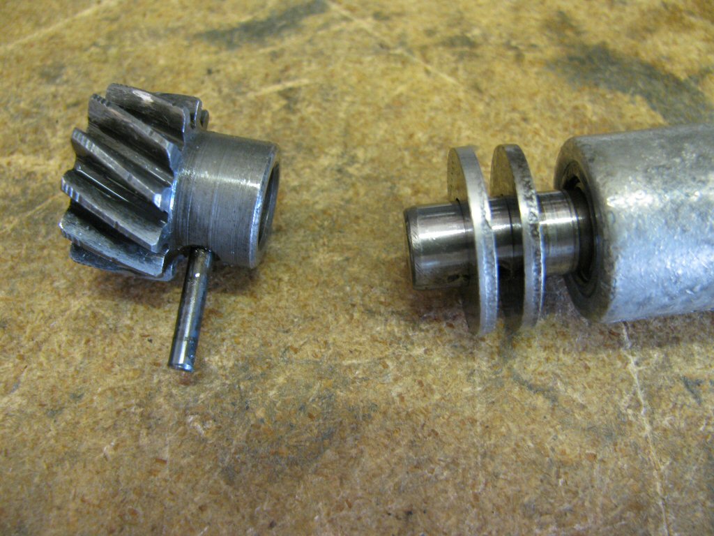
Then the shimming washer (nearest the drive gear) and the spacer washer (furthest from the drive gear). Typically the shimming washer is much thinner than the one shown. However, this distributor was previously rebuild and this shimming washer was fit in place.
Photo courtesy of Gregory Bender.
Here is a larger photo of rotating shaft starting to be removed.
Photo courtesy of Gregory Bender.
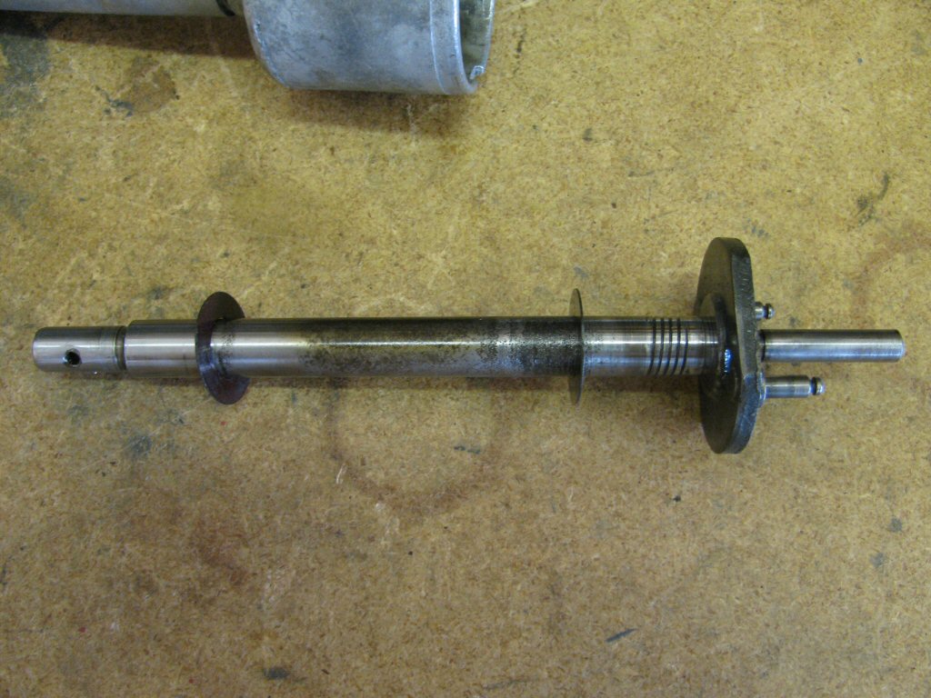
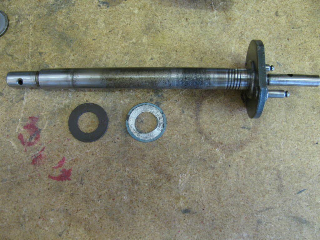
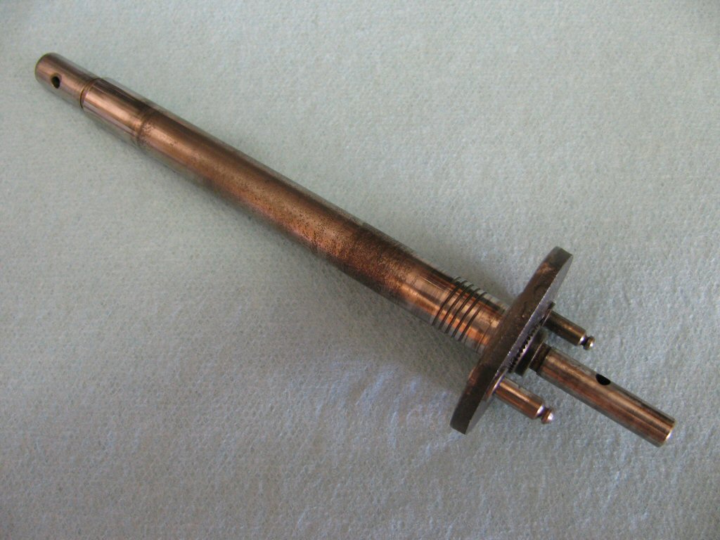
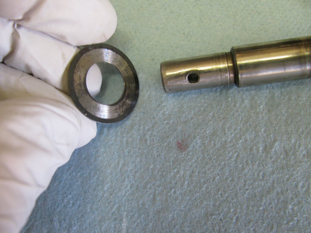
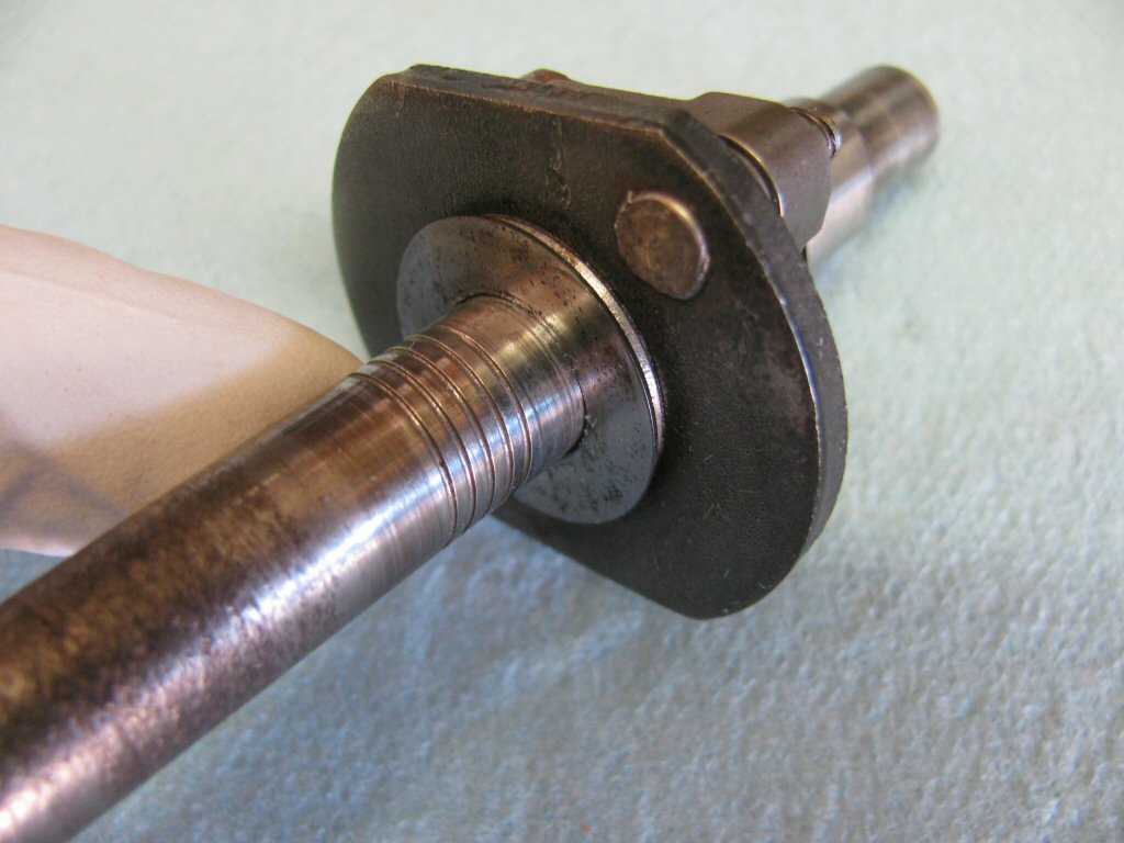
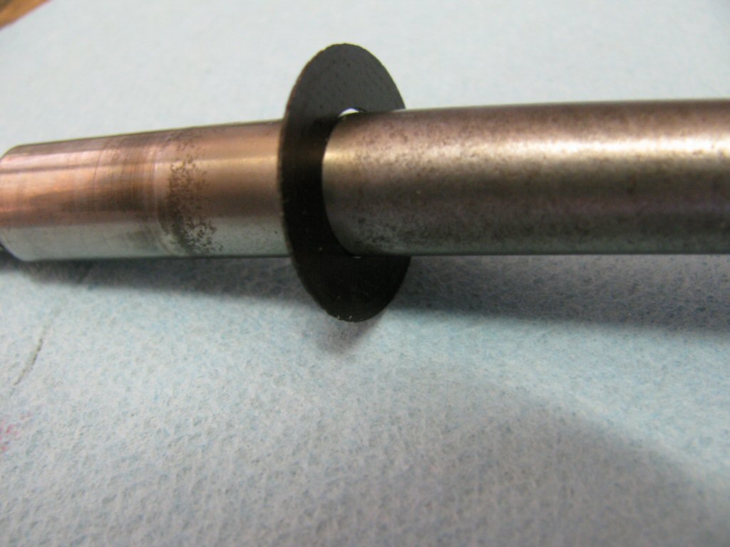
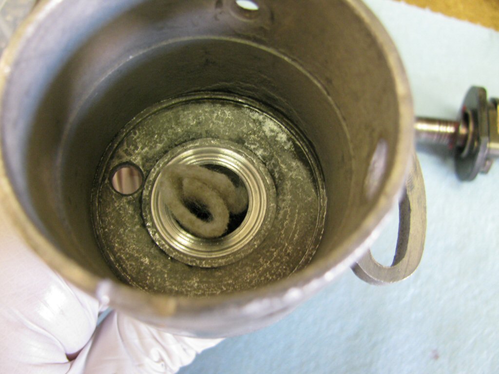
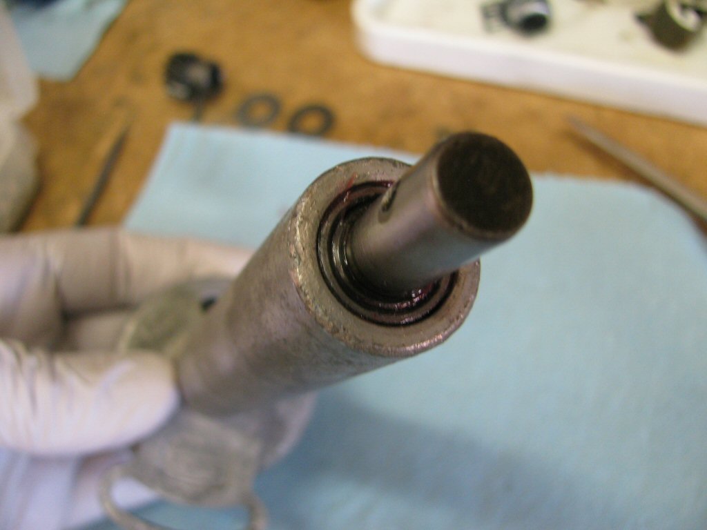
Here is the rotating shaft with the bakelite washer and a thin flat washer. Note that the bakelite washer is furthest from the top of the rotating shaft; the thin flat washer is positioned at the top of the shaft.
Photo courtesy of Gregory Bender.
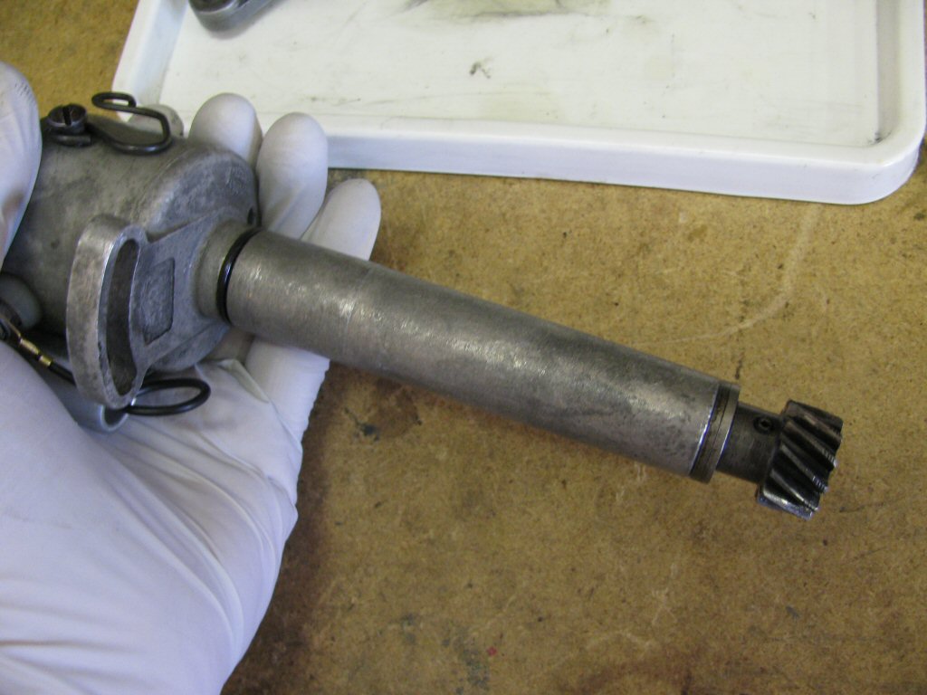
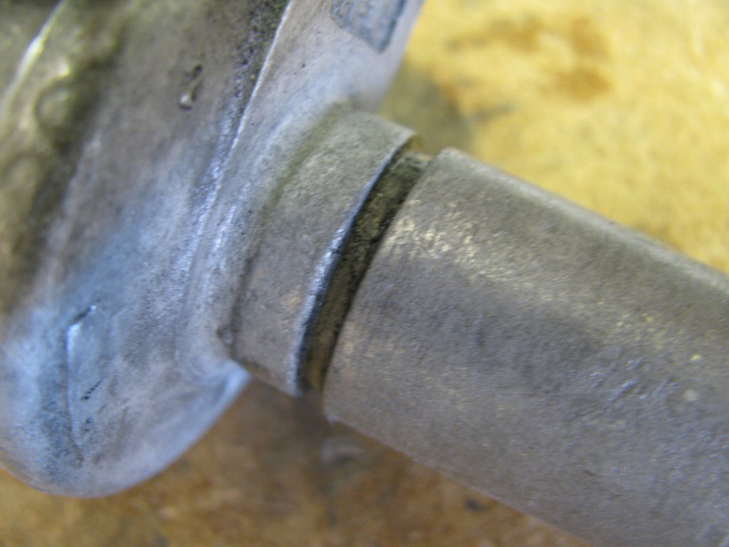
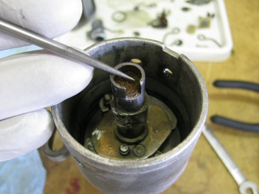
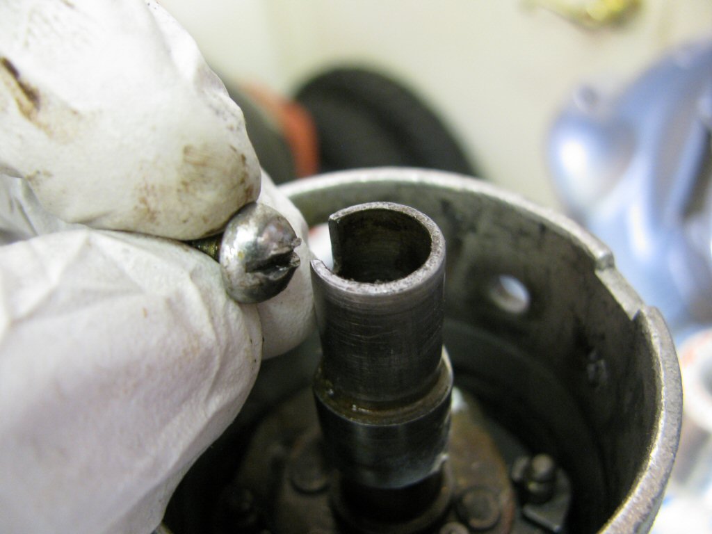
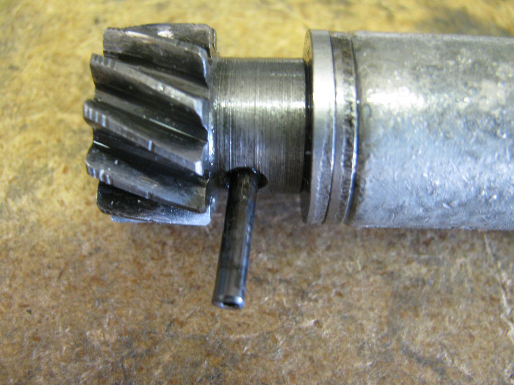
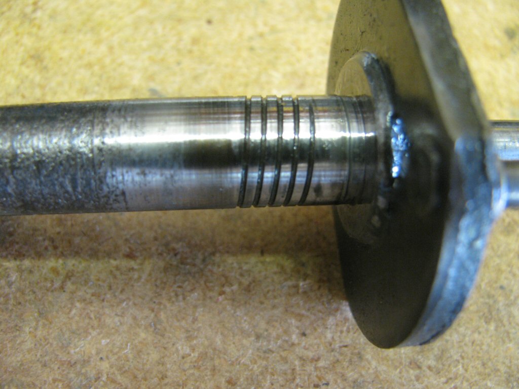
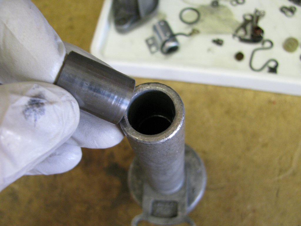
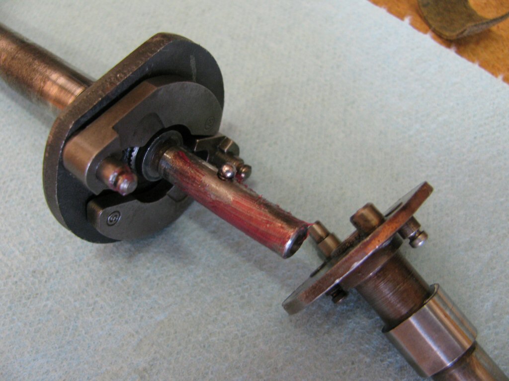
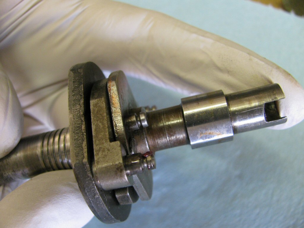
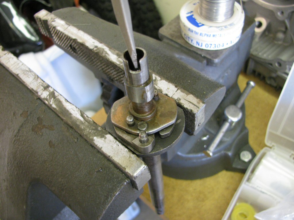
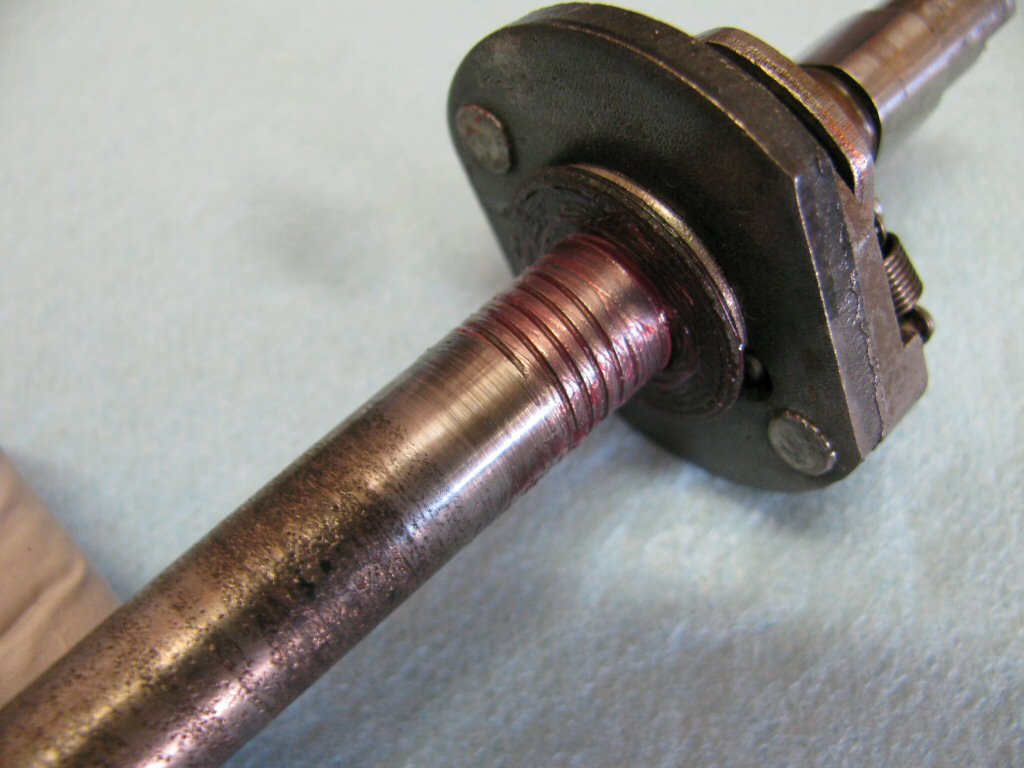
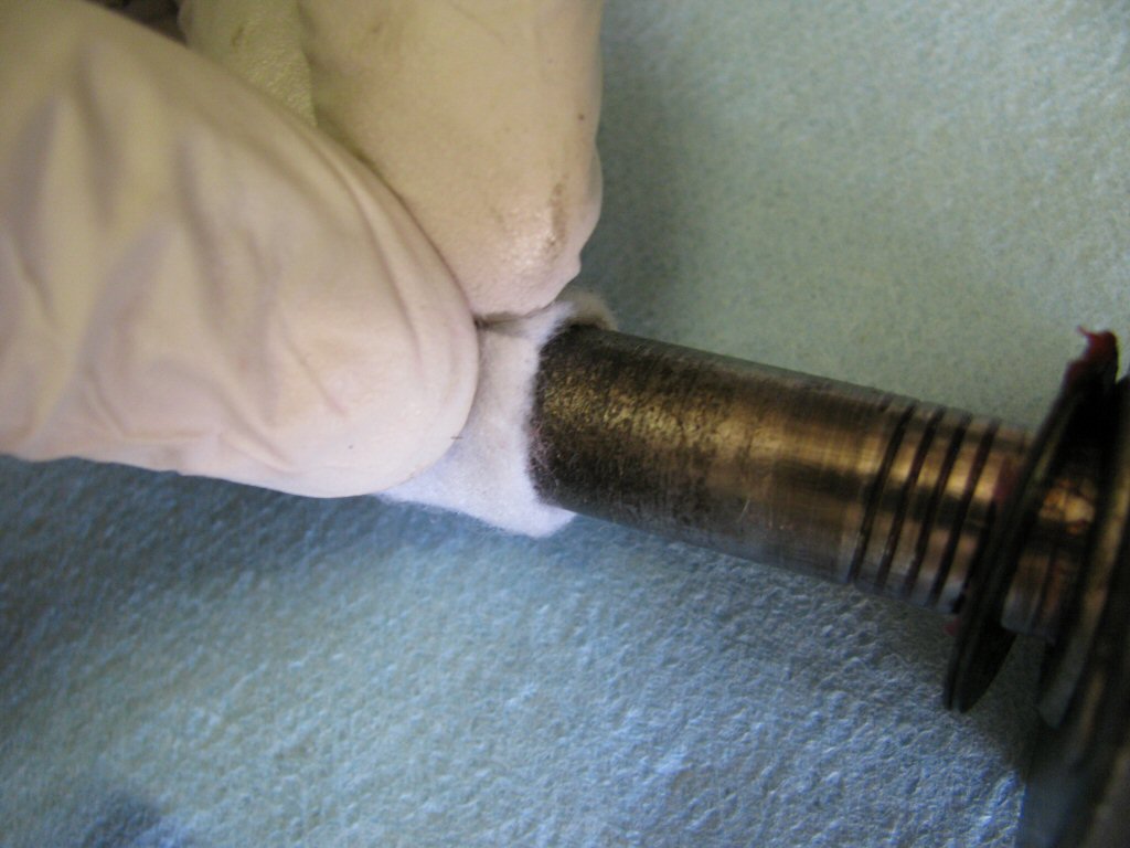
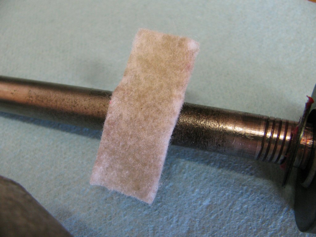
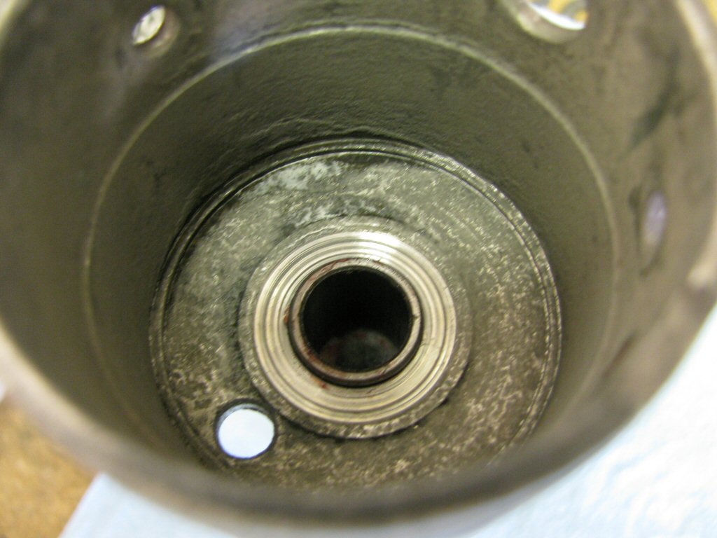
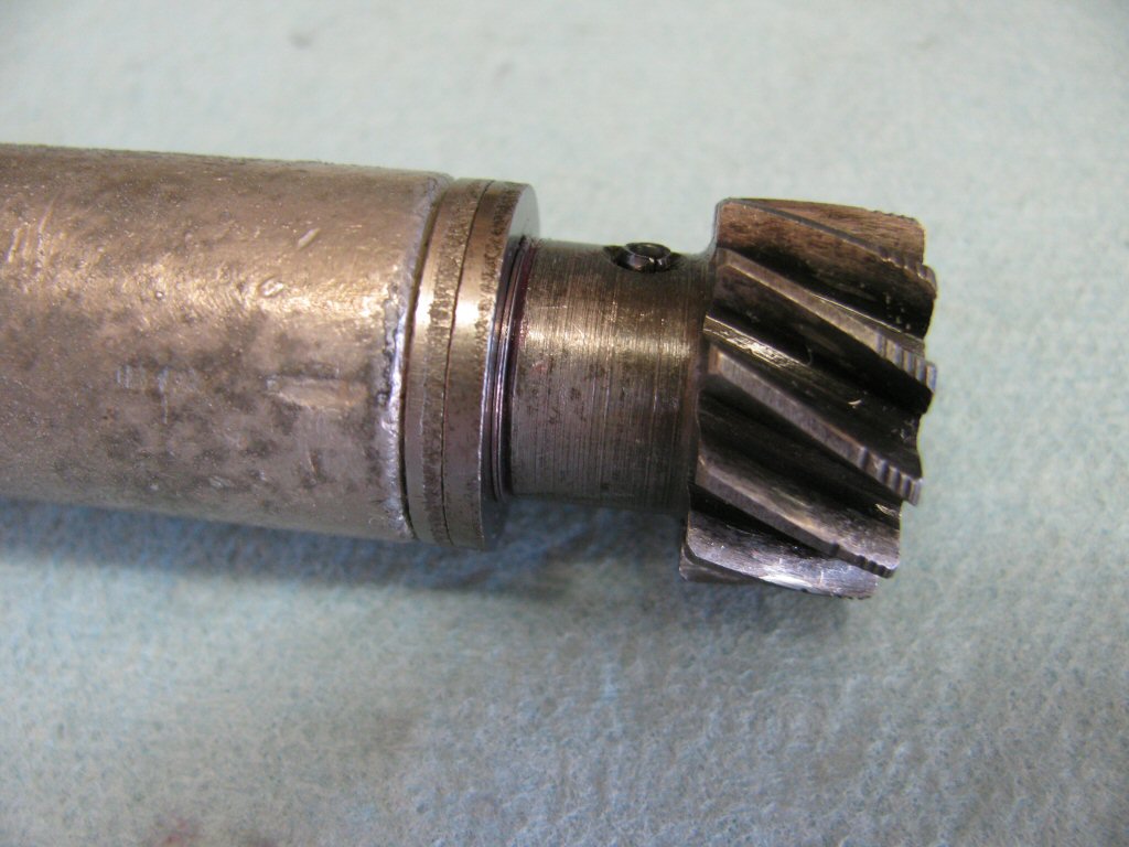
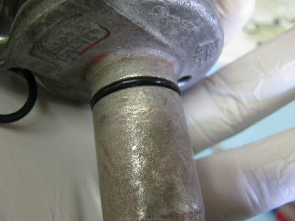
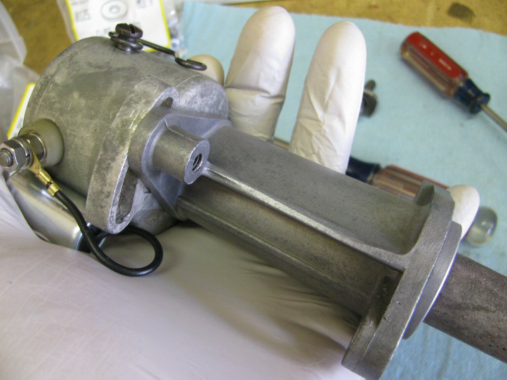
Note these spiral cuts. The purpose of these cuts is to direct oil back down into the engine to help prevent oil from migrating into the top of the distributor body.
Photo courtesy of Gregory Bender.
Another photo of the rotating shaft and washers.
Photo courtesy of Gregory Bender.
(Optional) Remove the bushing from the bottom of the distributor body.
Photo courtesy of Gregory Bender.
Remove the busing from the top of the distributor body.
Photo courtesy of Gregory Bender.
Remove the felt seal from the top of the distributor body.
Photo courtesy of Gregory Bender.
Assembling the distributor
Throughout assembly, I lube components that I assemble with a good quality synthetic grease (Mobil One).
After thoroughly cleaning all of the components, begin assembly with the rotating shaft.
Photo courtesy of Gregory Bender.
Lube the pivots and fit both advance weights. It does not matter which weight you fit to each pivot; the advance weights are interchangeable.
Photo courtesy of Gregory Bender.
Place a dab of grease on the tiny spring and insert it into the hole in the shaft.
Photo courtesy of Gregory Bender.
Place a dab of grease on the tiny ball bearing and place it onto the spring.
Photo courtesy of Gregory Bender.
Here is the advance mechanism that will be fit.
Photo courtesy of Gregory Bender.
Start to slide the advance mechanism onto the rotating shaft.
Photo courtesy of Gregory Bender.
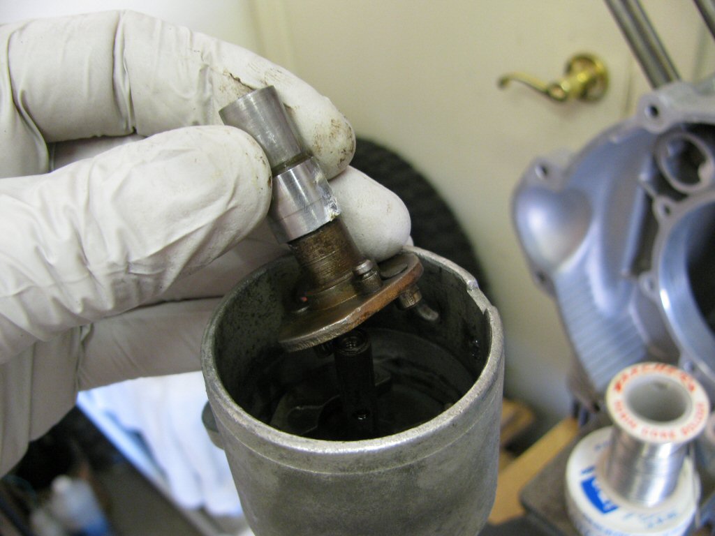
Hold down the tiny ball bearing and spring with your finger and then slide the advance mechanism over the ball bearing, moving your finger back as the advance mechanism moves over the ball bearing.
Photo courtesy of Gregory Bender.
You'll note that the two pins on the bottom of the advance mechanism are not of equal length.
Photo courtesy of Gregory Bender.
You'll also note that there is a hole in the bottom of the plate that is attached to the rotating shaft.
Photo courtesy of Gregory Bender.
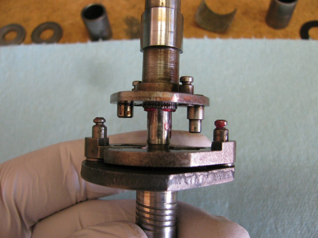
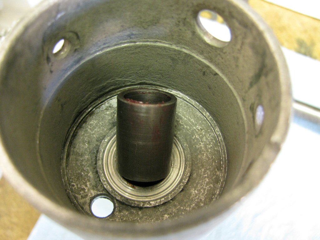
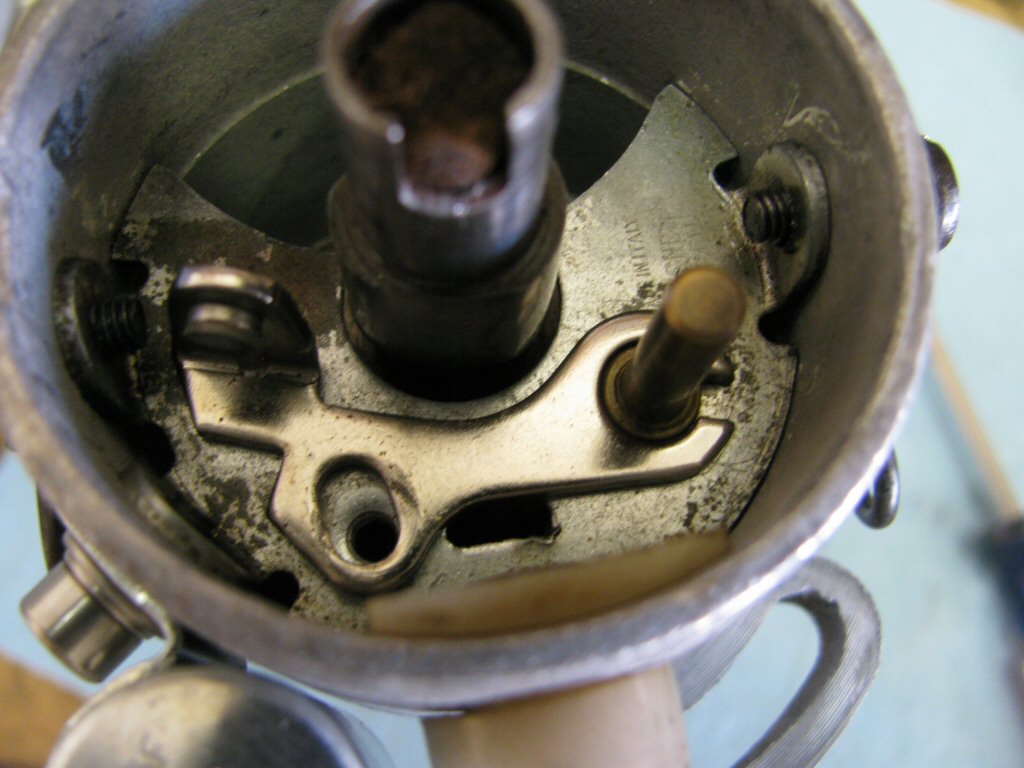
Slide the advance mechanism fully in place such that the longer pin fits into the hole in the plate. Both pins will also interface with the slots in the advance weights.
Photo courtesy of Gregory Bender.
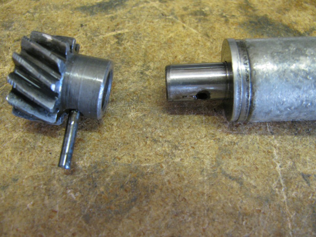
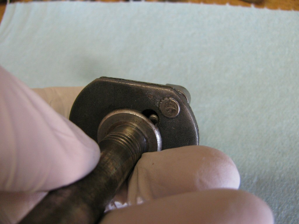
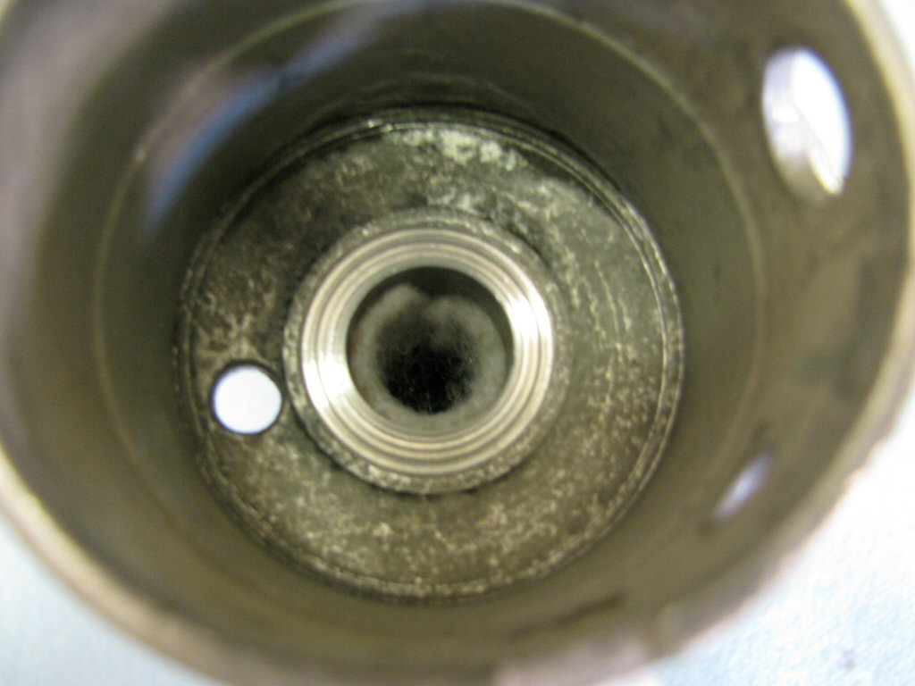
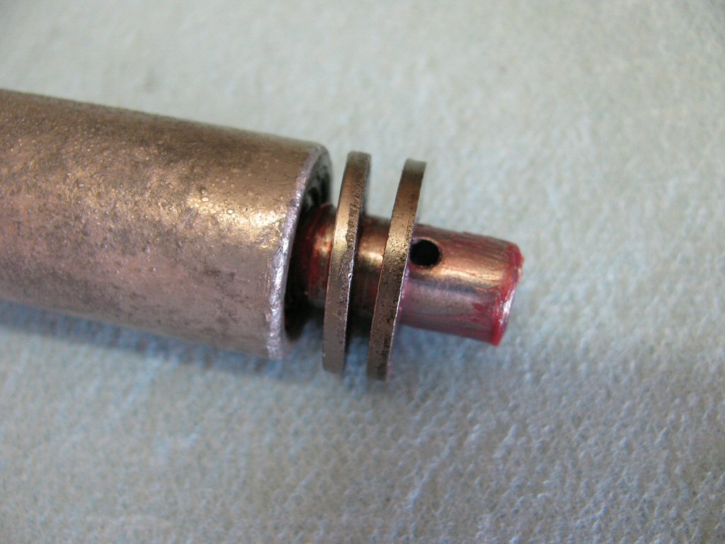
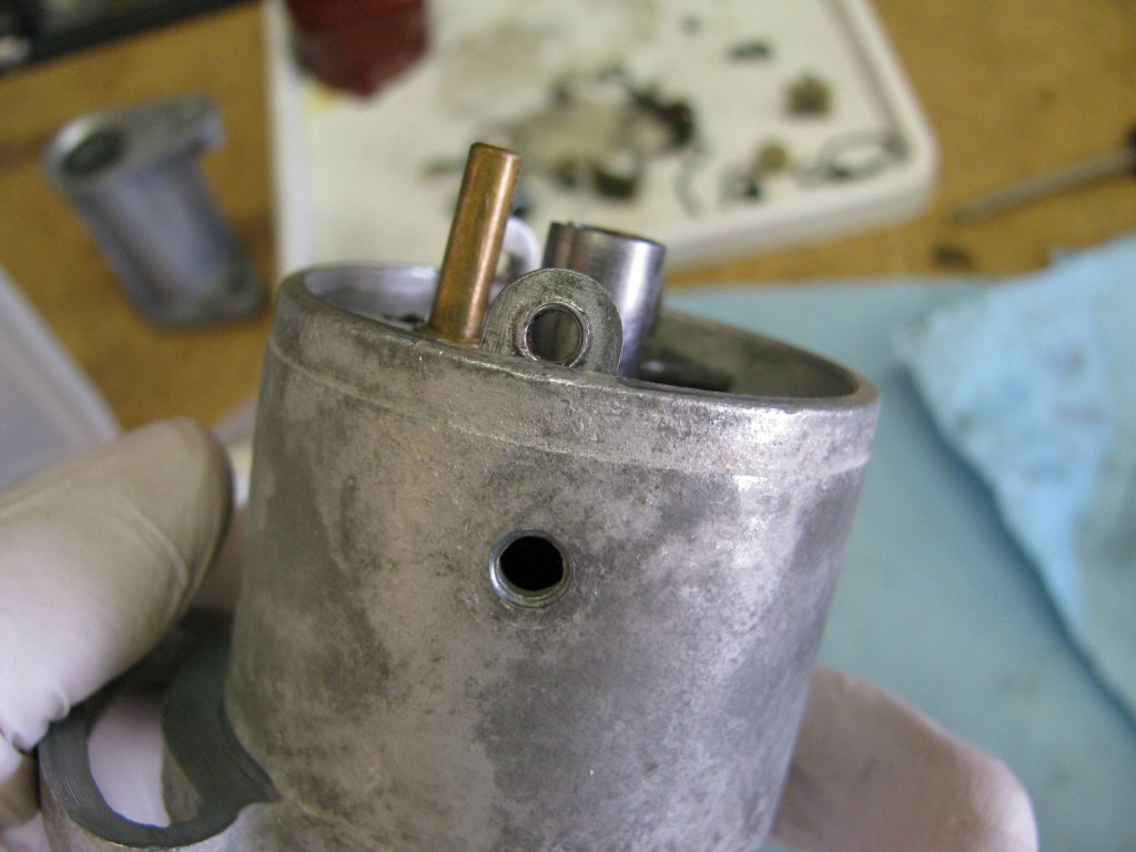
You can see the longer pin through the bottom hole. This longer pin limits the total advance and prevents the advance weights from jamming against the sides of the distributor body, should the advance springs break.
Photo courtesy of Gregory Bender.
Fit the screw to secure the advance mechanism to the rotating shaft.
Photo courtesy of Gregory Bender.
Here is another way to secure the rotating shaft.
Photo courtesy of Gregory Bender.
Fully tighten the screw.
Photo courtesy of Gregory Bender.
Then place the small felt plug above the screw.
Photo courtesy of Gregory Bender.
Push the small felt plug fully in place.
Photo courtesy of Gregory Bender.
Time to fit the advance springs.
Photo courtesy of Gregory Bender.
Fit one advance spring.
Photo courtesy of Gregory Bender.
Fit the other advance spring. It does not matter which spring goes onto each advance weight.
Photo courtesy of Gregory Bender.
Place the thin flat washer onto the rotating shaft.
Photo courtesy of Gregory Bender.
Slide it up against the underside of the plate.
Photo courtesy of Gregory Bender.
Place the bakelite washer onto the rotating shaft.
Photo courtesy of Gregory Bender.
Slide it up against the thin flat washer. Note that I've lubricated the washers and shaft.
Photo courtesy of Gregory Bender.
The felt shaft seal should be replaced. This seal helps keep oil from escaping through the top of the distributor and helps keep the shaft lubricated.
Photo courtesy of Gregory Bender.
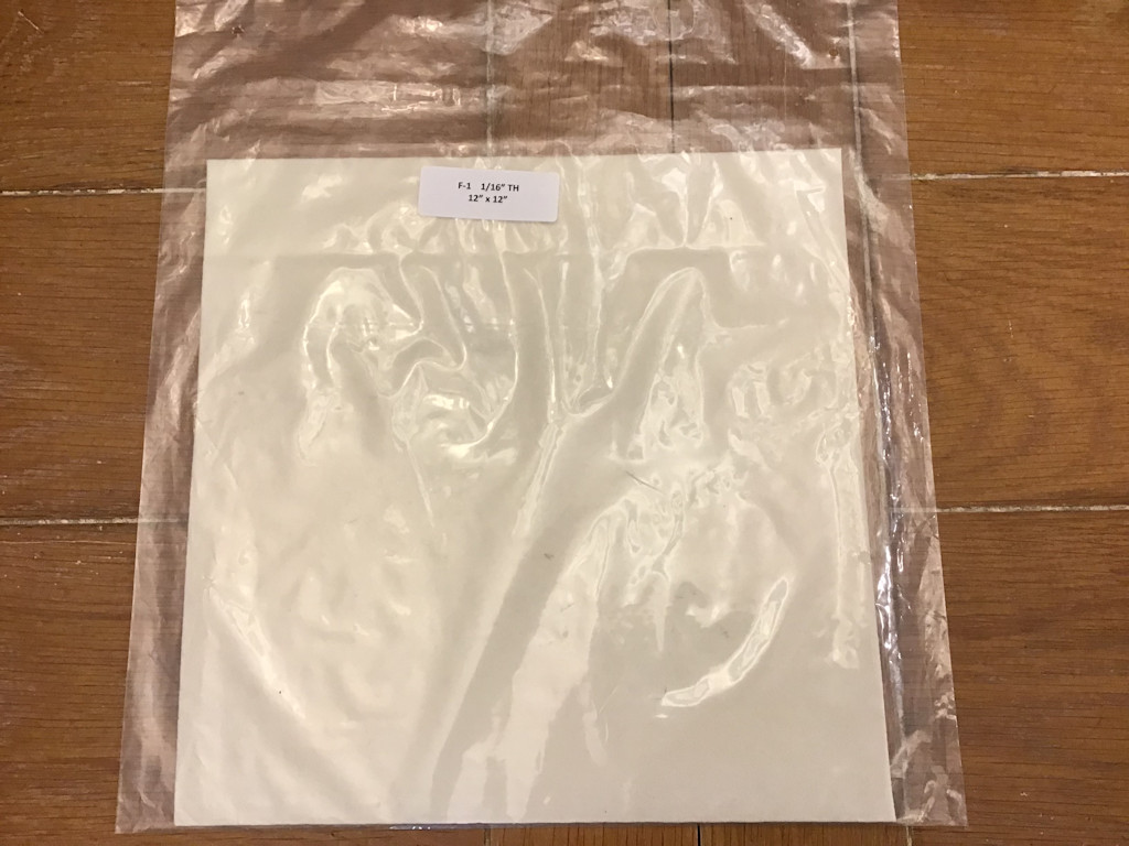
Thanks to Dan Eberhardt for sending me this additional information about the felt he uses:
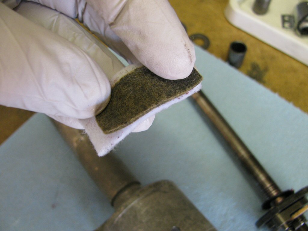
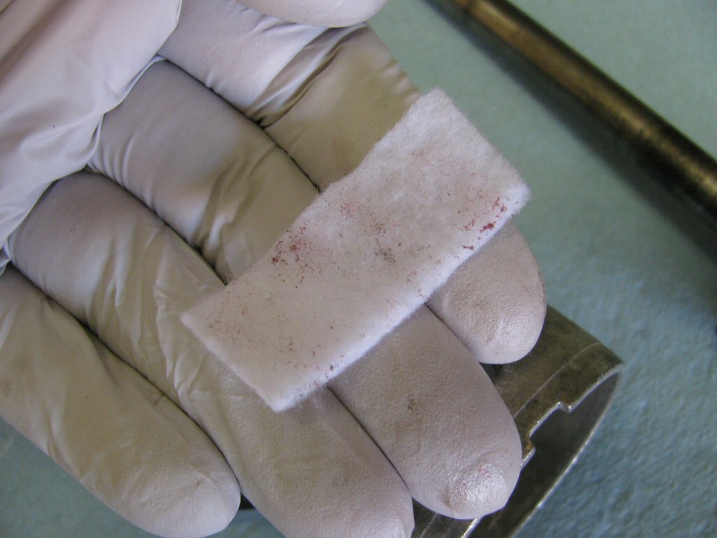
I have some more useful information to pass along regarding the type of felt to use for the distributor shaft. Several years ago I was able to buy felt at the local hobby stores (Hobby Lobby, Michaels etc.) that wasn't the best but did work for the distributor shaft. However, I purchased some recently and had to replace it in just a few miles and thought maybe I misaligned it when installed so installed another one only to have it begin passing oil in just another few hundred miles. Took the distributor apart again very carefully and the felt was located properly but it was evident that it was not expanding like a felt seal should! Did some research and discovered quality felt should contain mainly wool. McMaster-Carr to the rescue once again (Part #8334K35). It is 1⁄16 inch thick, has a durometer of 35A and a tensile strength of 500 PSI and only costs USD $10.46 for a 12 inch × 12 inch sheet. The seals fit well when cut to 16 mm × 45 mm.
Here is the felt sheet.
Photo courtesy of Dan Eberhardt.
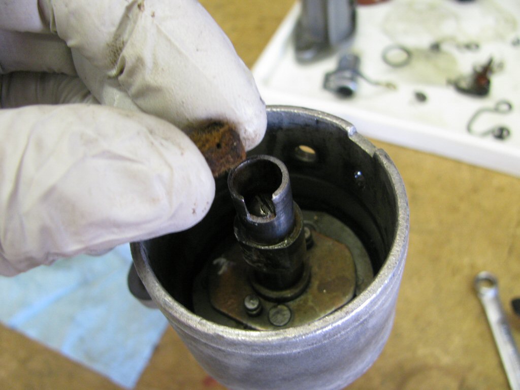
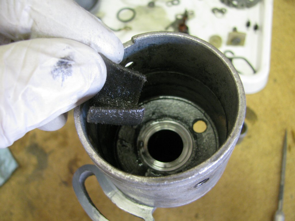
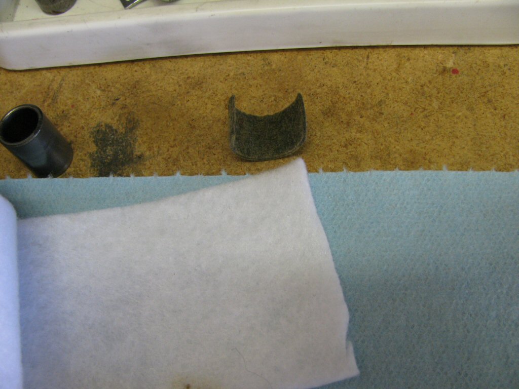
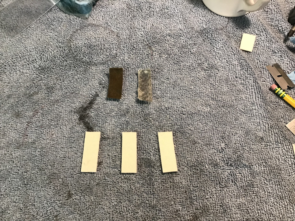
Here's an original old seal on the left with thousands of miles and here's a new seal on the right made with Craft Store felt after just a few hundred miles along with some seals made from the Good Stuff.
Photo courtesy of Dan Eberhardt.
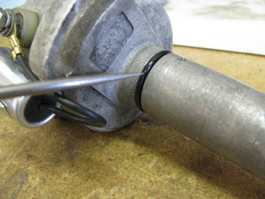
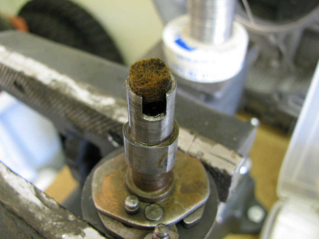
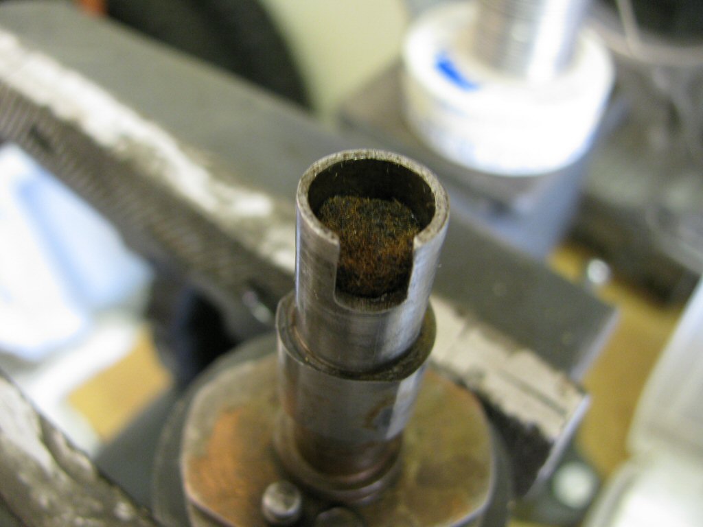
Cut the felt to size. You'll note the new piece is longer than the old piece. The old piece did not fully wrap around the shaft. This is common after 40 years - the old felt shrinks. The felt can also become stiff, full of rust, etc.
Photo courtesy of Gregory Bender.
Here is the felt cut to size.
Photo courtesy of Gregory Bender.
Here is the felt wrapped around the shaft. Note that it fully wraps the shaft.
Photo courtesy of Gregory Bender.
Soak the felt in oil. Do not install it dry.
Photo courtesy of Gregory Bender.
Wrap the felt as shown and insert it into the top of the distributor body.
Photo courtesy of Gregory Bender.
Using a screw driver or similar, get the felt positioned around the ID of the distributor body.
Photo courtesy of Gregory Bender.
Insert the bushing.
Photo courtesy of Gregory Bender.
Pushing the bushing into place.
Photo courtesy of Gregory Bender.
Fit the rotating shaft (fully lubricated). You'll note the bottom bushing is also in place.
Photo courtesy of Gregory Bender.
Fit the spacing washer and shimming washer into place (lubricated).
Photo courtesy of Gregory Bender.
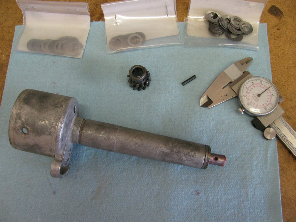
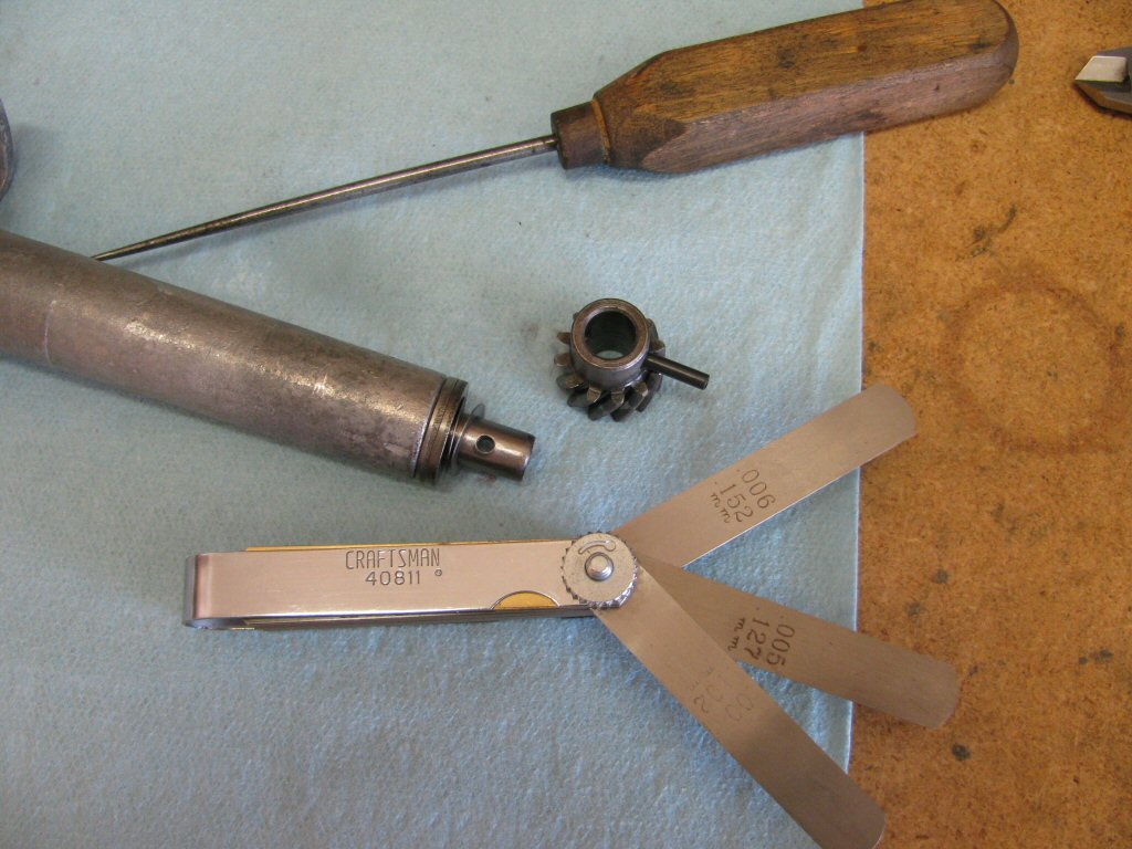
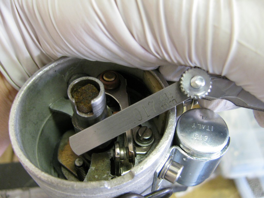
Fit additional shims under the drive gear to achieve a clearance of 0.1 mm to 0.15 mm (~0.004 inch to ~0.006 inch). Every distributor that I've rebuilt has had way too much clearance. Shimming the shaft properly is an important step.
Photo courtesy of Gregory Bender.
My lifetime supply of replacement roll-pins to secure the drive gear to the rotating shaft. See sizing information here.
Photo courtesy of Gregory Bender.
Shims and drive gear.
Photo courtesy of Gregory Bender.
Tools I use to check the clearance. The ice pick is a great size to get close to the needed shims prior to fitting the roll pin. Final adjustment is done with the actual roll pin.
Photo courtesy of Gregory Bender.
Drive gear back in place.
Photo courtesy of Gregory Bender.
Another view of the drive gear back in place.
Photo courtesy of Gregory Bender.
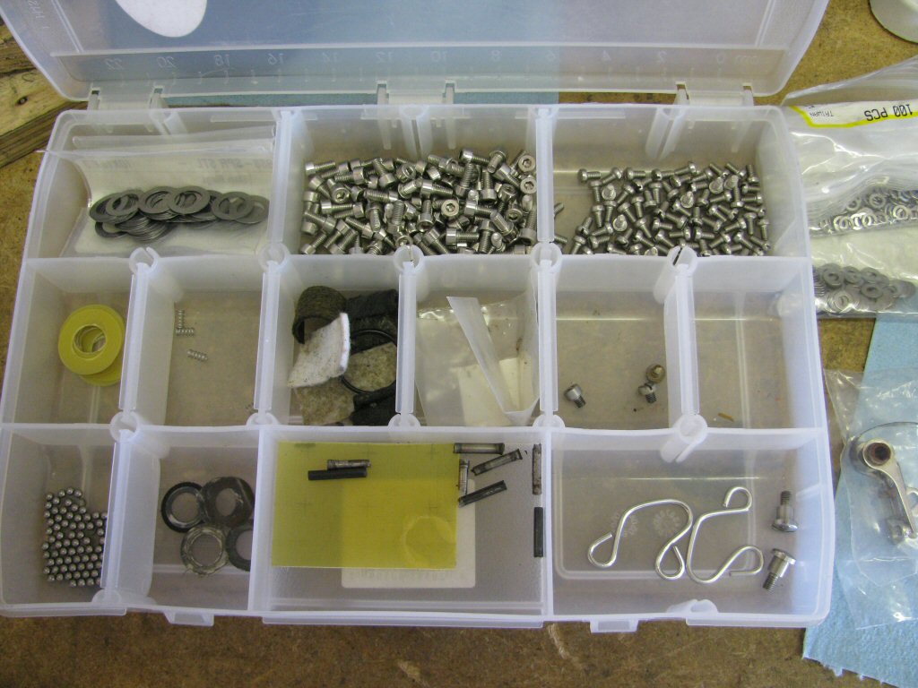
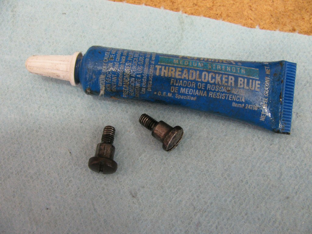
I like to replace the original fasteners with stainless replacements. Here is my lifetime supply of distributor related pieces and parts (including replacement bakelite washers!). I made the replacement bakelite washers using modern Garolite material that I purchased (McMaster-Carr part number 8667K111).
Photo courtesy of Gregory Bender.
Fit the points-plate so that the two threaded holes match the two holes in the distributor body.
Photo courtesy of Gregory Bender.
The single threaded hole lines up with the single hole in the distributor body.
Photo courtesy of Gregory Bender.
One of the very few places I use blue Loctite. Just a very light application on the threads of the shoulder screws.
Photo courtesy of Gregory Bender.
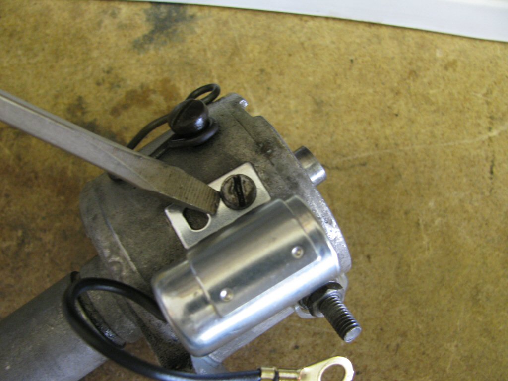
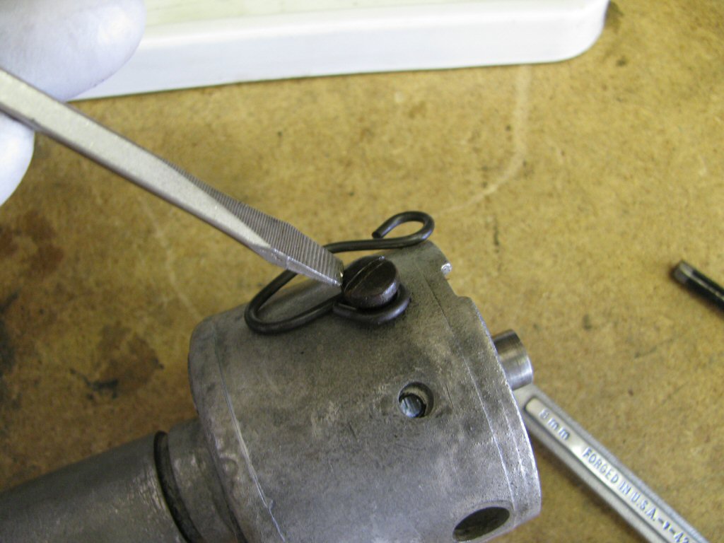
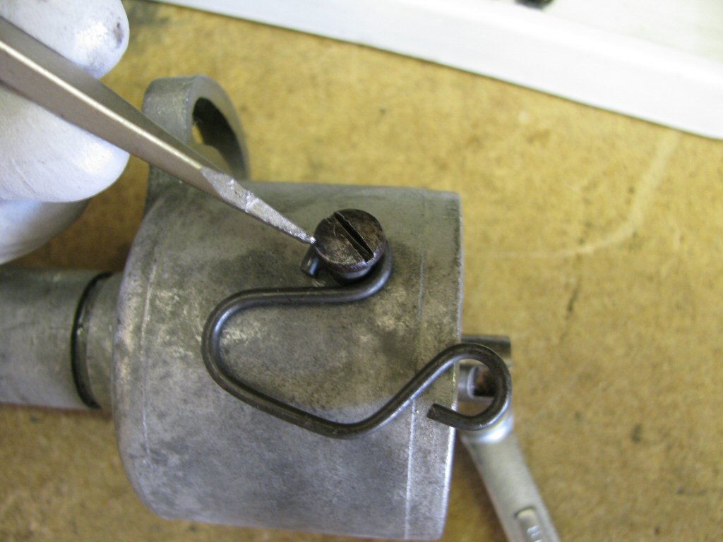
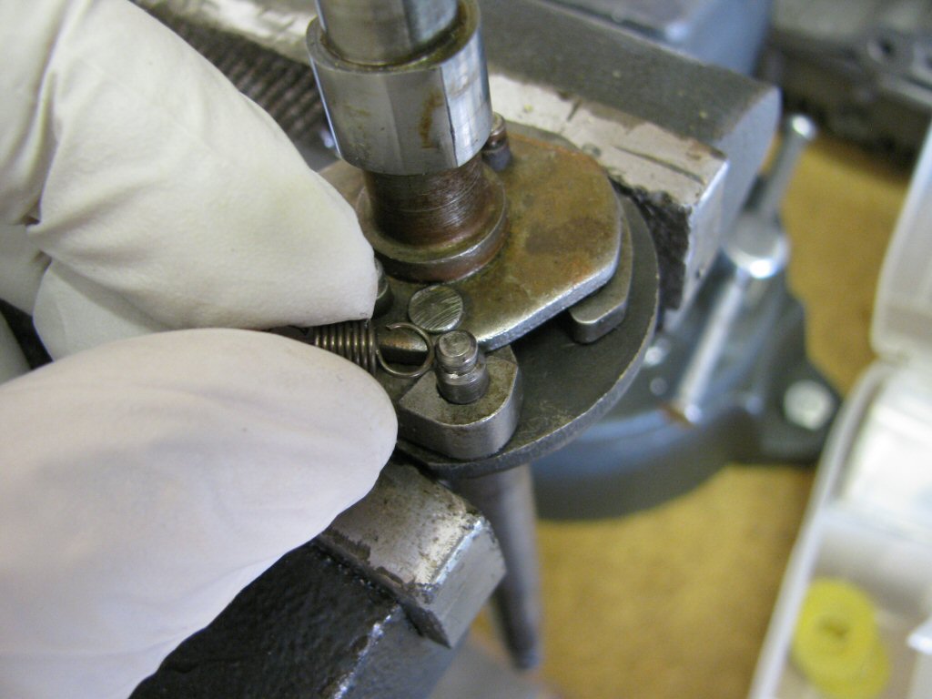
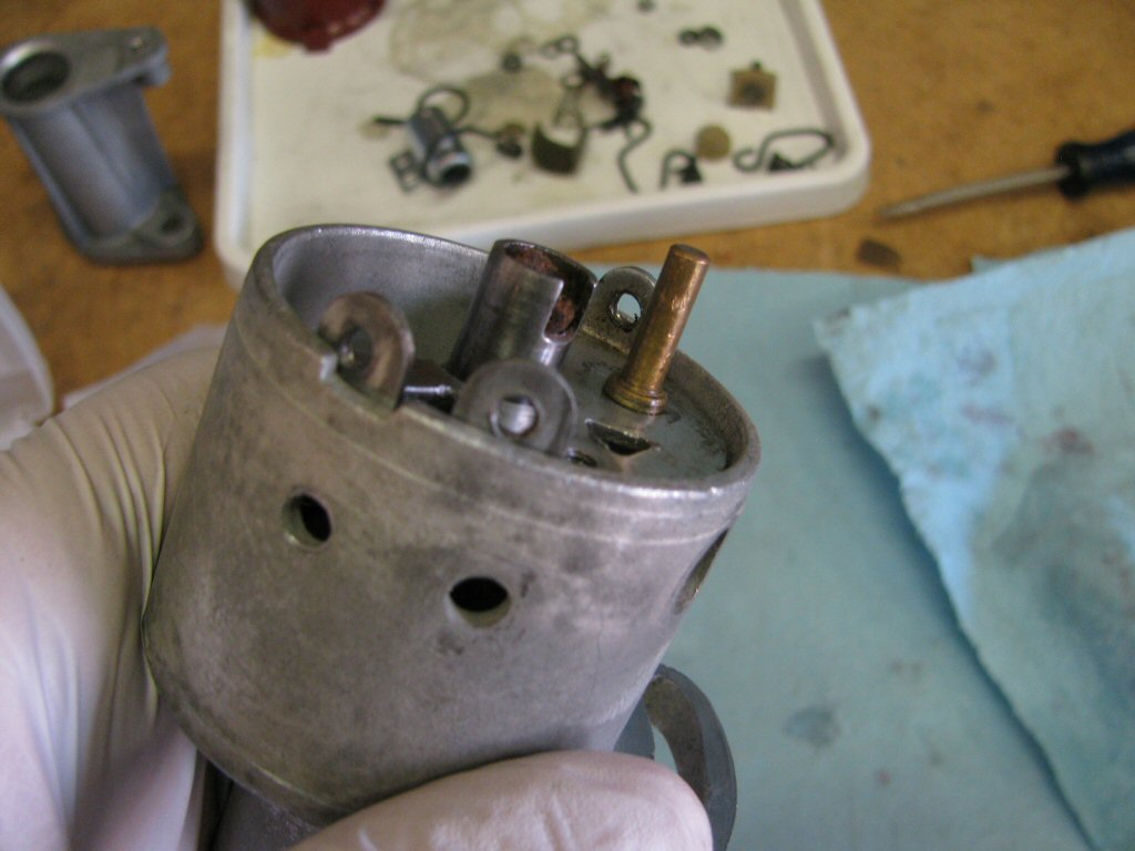
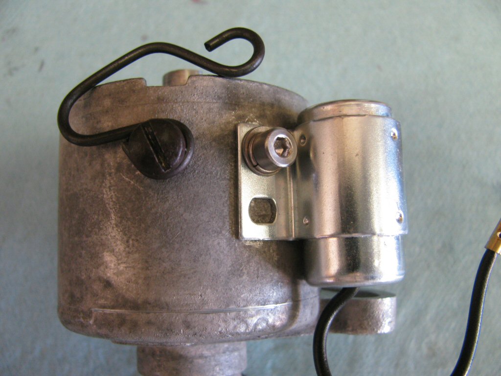
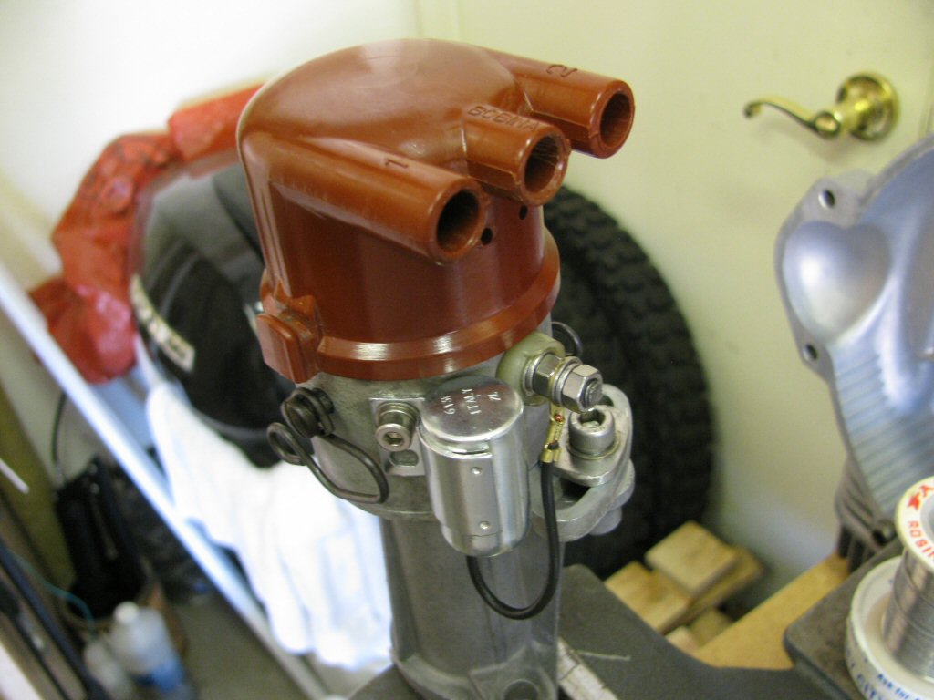
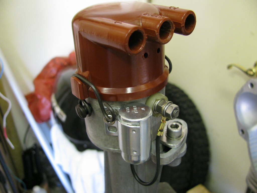
On the side with two threaded holes, I fit the spring clip and condenser as shown. I prefer the spring clip to face this direction as I find it much easier to move into place when the distributor is mounted on the engine case.
Photo courtesy of Gregory Bender.
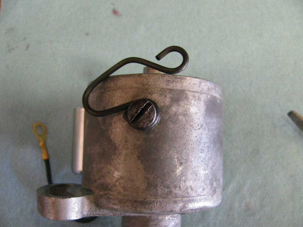
On the side with one threaded hole, I fit the spring clip as shown. Again, I prefer the spring clip to face this direction as I find it much easier to move into place when the distributor is mounted on the engine case.
Photo courtesy of Gregory Bender.
Fit the bolt and inner plastic insulation piece through the side of the distributor body.
Photo courtesy of Gregory Bender.
Note how the plastic insulation fits as well as how the bolt fits through the plastic insulation.
Photo courtesy of Gregory Bender.
Fit the outer plastic insulation piece. Again, note the keyed fitment with the bolt.
Photo courtesy of Gregory Bender.
Fit the base of the contact breaker as shown.
Photo courtesy of Gregory Bender.
Fit the screw in place. I like to use both a flat washer and a lock washer under the head of the screw.
Photo courtesy of Gregory Bender.
Fit the arm of the contact breaker as shown. Note how the metal tab fits under the head of the bolt.
Photo courtesy of Gregory Bender.
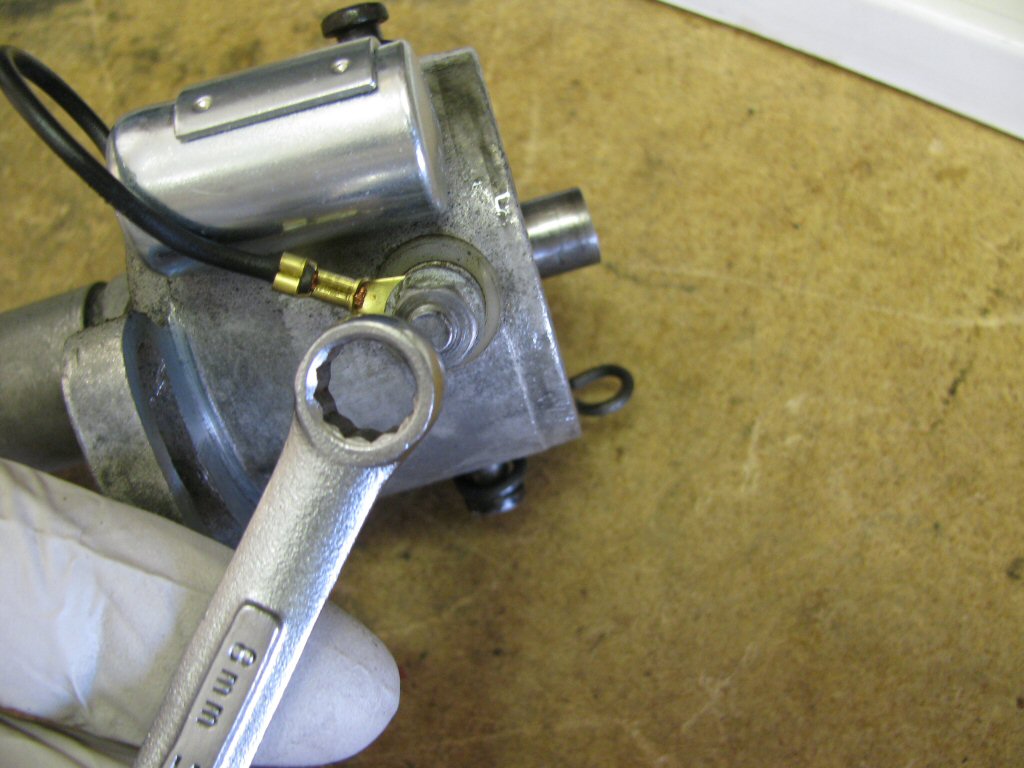
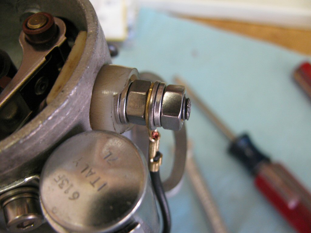
Fit and tighten the nut. I use both a flat washer and a lock washer under the nut. Tighten securely, but do not over tighten and break or deform the plastic insulation.
Photo courtesy of Gregory Bender.
Fit the wire from the condenser and then secure in place with a flat washer, lock washer, and nut.
Photo courtesy of Gregory Bender.
Fit a new O-ring to the distributor body.
Photo courtesy of Gregory Bender.
Slide the distributor base onto the distributor body.
Photo courtesy of Gregory Bender.
Secure the distributor body to the distributor base with the bolt and washer as shown. Again, a special washer was fabricated to spread out the forces on the soft aluminum of the distributor body. A very worthwhile upgrade.
Photo courtesy of Gregory Bender.
Adjust the clearance between the breaker points. I place the breaker points on the wide lobe and set to 0.017 inch of clearance.
Photo courtesy of Gregory Bender.
Lubricate the lobes with dielectric grease.
Photo courtesy of Gregory Bender.
The assembled internals.
Photo courtesy of Gregory Bender.
Fit the rotor.
Photo courtesy of Gregory Bender.
Rotor fit in place.
Photo courtesy of Gregory Bender.
Fit the distributor cap. Note that the bottom of the distributor cap is notched to fit into a corresponding notch in the body of the distributor.