Dash indicator lights - Head light indicator or High beam indicator?
Moto Guzzi V700, V7 Special, Ambassador, 850 GT, 850 GT California, Eldorado, and 850 California Police models
Created:
Updated:
// //
Thanks to Patrick Hayes, Carl Allison, Charlie Mullendore of Antietam Classic Cycle, and Carl Krall for investigating this information via private communications with me and for posting the information on the old Yahoo! Loopframe_Guzzi news group (which has now moved to Groups.io).
Patrick Hayes' original post after initial investigation with Carl Allison, Charlie Mullendore, and Gregory Bender
Carl Allison of Oklahoma has produced some lovely, color-coded wire diagram plans for most Guzzi models. These plans are hosted in duplicate at Gregory Bender's this old tractor site and also on Guzzitech.com. They are a very handy aid for any electrical diagnostic or modification work.
(CAUTION: Never look at the plans you might find on a pacbell server. Carl has been off that account for many years. He can't update or edit or delete those files. Pacbell refuses to take them down or give him access to take them down. They are obsolete but still show up in net searches.)
I have discovered a few anomalies in some of the plans and have been working with Carl to perfect and update the color plans. We have discovered something in the Loop frame Series that seems VERY WRONG in electro/mechanical design and we need further input from end users. To paraphrase Capt. Louis Renault in Casablanca, I'm shocked to hear that there are errors in Guzzi wire plan design! Shocked I tell you!
We are referring to 750 and 850 loop frames. Please look at your parts if you happen to have them opened up. Please look at any library wire diagrams if your bike is intact. Please look at the fuse panel inside the headlamp housing which contains 9 fuses.
Fuse #3 gets a RED power feed wire coming from the ignition switch. That power comes from the battery, through the key switch and into the fuse panel without any fused protection. The fuse block has an internal bridge structure on its back side which connects the tops of all of the fuses from #3 through to #7. So, all five of those ganged fuse positions are HOT on the top side whenever the key switch is on.
Now to the mystery. The TOP of Fuse #4 has a BLUE/BLACK wire which feeds power to the ignition coil. The TOP of Fuse #5 has a similar BLUE/BLACK wire which feeds power to the starter button and starter relay circuit. Both of these feed positions on the TOP of the fuse plate are hot as soon as the key is turned on. AND THEY ARE BOTH NOT PROTECTED BY DOWNSTREAM FUSES!!!!! Any short circuit in either of those wires will result in some serious melting somewhere.
If you have any further information or comment about these two circuits, we'd like to hear it so that the plans can be corrected. If there is some logical electrical reason to design this way, we'd like to hear that so that we know the plans are accurate. We have seen several Loop frame plan variants in books by several publishers. They all seem to agree in this wire anomaly. It just doesn't make good engineering sense. But, if that is truly the way Guzzi designed it, then we want to reaffirm that design.
Marty Ray's input on the use of unfused circuits (Marty sent this to me via a private communication)
You make a big point about unfused circuits in the ignition area, I wanted to point out that this style of wiring is common in older school electrical systems, where typically only the branch accessory circuits are fused. Common unfused circuitry in older vehicles are: lamps, horn, ignition, dynamo, control box. Feel free to rewire as you see fit, but I don't think Guzzi was too far out of normal practice for the time. Perhaps the thinking was to only fuse circuits that were less critical to operation.
Carl Krall's reply to Patrick Hayes
I did notice that the high beam indicator wire is in the wrong place on the diagram I downloaded. If placed where the diagram shows, it is a headlight indicator. Needs to go over to the Siamesed connection off the high beam wire.
Will go have a look at those wires you mention, seems like there is ample room for them to be off the bottom row. Some of my fuses aren't protecting anything at all, and I'm beginning to understand why.
Gregory Bender's reply to Carl Krall
There is indeed some confusion as to what that indicator light is really supposed to indicate.
I've seen original wiring diagrams that show both scenarios: as a lights are on indicator AND as a high beam indicator.
The labels on the dash and/or gauges don't help matters, either. The single gauge speedometer uses a lights label (perhaps to indicate lights are on) whereas the civilian 2-gauge dash uses an H label (perhaps to indicate high beam).
Then, there is my personal preference to use that indicator light as a turn signals are flashing indicator (also known as a hey dummy, turn off your turn signals before someone believes you and does a lefty in front of you and you earn the nickname T-bone for a very good reason indicator).
Oh well...I bet Guzzi put them in a variety of configurations leaving the factory. At least they are easily changed to indicate whatever a person wants :>
Patrick Hayes's reply to Carl Krall
I'm looking at the 750 CIVILIAN Ambassador USA wire plan. I see what you refer to. Actually, from the plan and from the descriptive text, Guzzi apparently never intended it as a HIGH BEAM indicator on the Civilian bike, but merely as a HEADLIGHTS ON indicator. How odd! Likely some Italian DOT regulation held over from cars. One would think that in the middle of the night you would be able to tell if your headlights were on or not without the guidance of a little red idiot light! None the less, since Guzzi calls it a LIGHTS INDICATOR, the diagram is correct and the wire is in the correct (but not best) position.
As you advise, it would be quite easy to relocate the wire so that the indicator bulb only glows when the HIGH BEAM is ON, a much more logical function. The 750 POLICE Ambassador wire plan does relocate this wire as you have suggested so that it does become a true HIGH BEAM indicator and they do call it a HIGH BEAM indicator in the text.
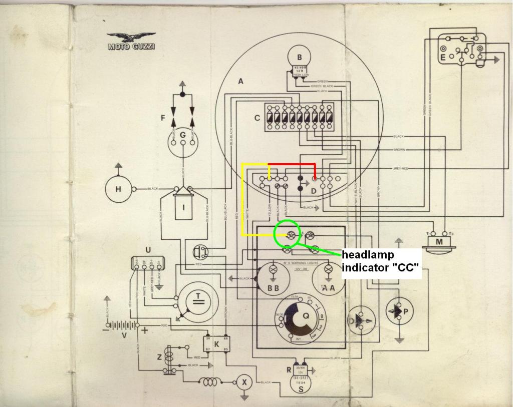
For anyone wishing to make this modification to a Civilian Ambassador, I have posted a simple little diagram here:
Photo courtesy of Patrick Hayes.
If your wiring is stock, you will have a YELLOW/BLACK wire positioned as I have shown. I can't do BI-COLOR lines, so I only show it here in YELLOW. If you wish to alter for use as a HIGH BEAM indicator as described, just remove this wire from the connector panel in the base of your headlamp housing and relocate it to the new position as I have shown in RED. Your wire colors won't change, I am only using these colors for position contrast.
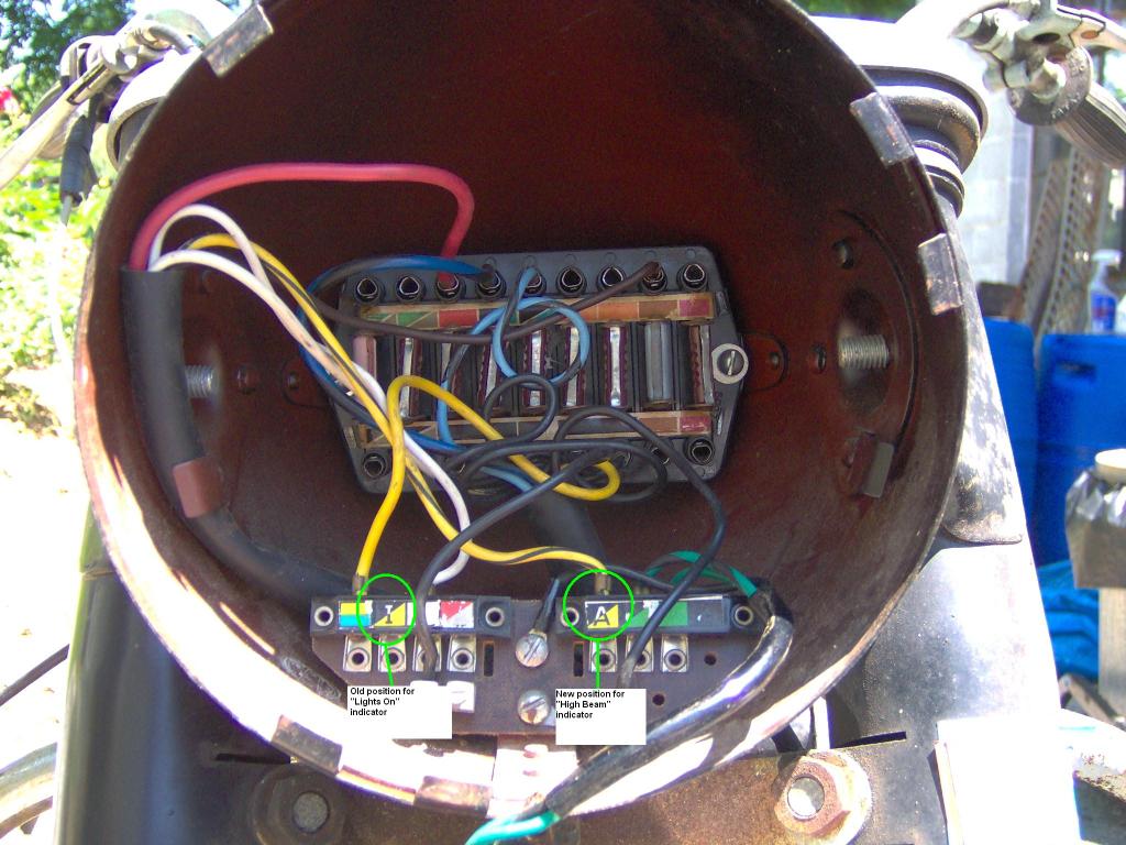
With permission, here also is a nice, clear photograph of the headlamp housing innards from Charlie Mullendore.
Photo courtesy of Patrick Hayes.
Note here that Guzzi has included color-coded stickers on the junction block. Conveniently, they show two YELLOW/BLACK positions even though the harness has only one YELLOW/BLACK wire. The left side YELLOW/BLACK position results in a lights on indicator. The right side YELLOW/BLACK position results in a high beam indicator.
Patrick Hayes' further investigation into the Italian language
Last week we were looking at some oddities on the loop frame wire diagrams. The wire plan includes one YELLOW/BLACK wire within the headlamp housing which ignites a warning light on the dash panel. The junction block in the headlamp includes TWO possible positions for this wire. On the Civilian bikes, the wire is factory installed in the I position and the warning light ignites whenever any headlamp in on. On the Police bikes, the wire is factory installed in the A position and the warning light ignites only when the HIGH BEAM is on.
So, what do the I and A positions mean in the original Italian?
Learned a new word this week. The I is for Iluminazione or lighting or lighting system. The A is for Abbagliante (ahb-baal-YON-tay). Means dazzling or brilliant and hence High Beam in vehicle applications.
See here for clarification:
Photo courtesy of Patrick Hayes.
No reason why any rewire project shouldn't move to the A position for a more logical application.