Rectifier (diode board) connections
Created:
Updated:
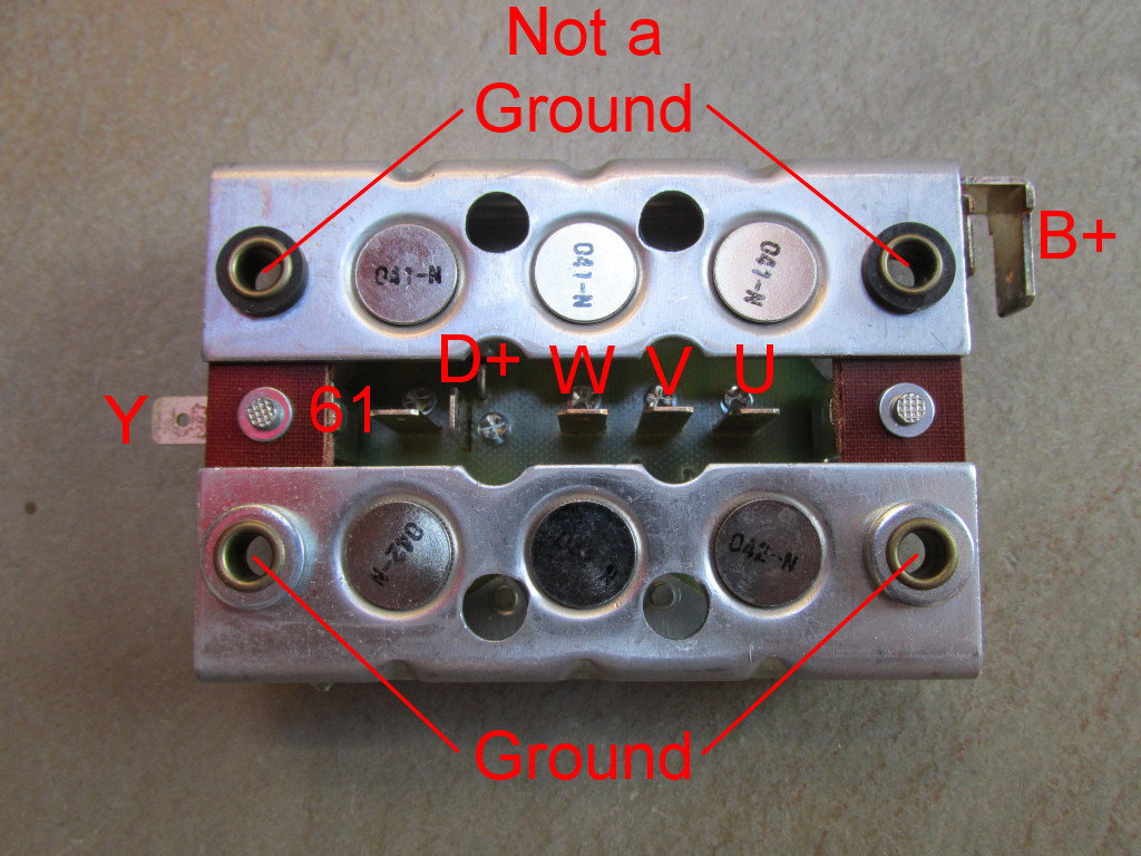
Photo courtesy of Gregory Bender.
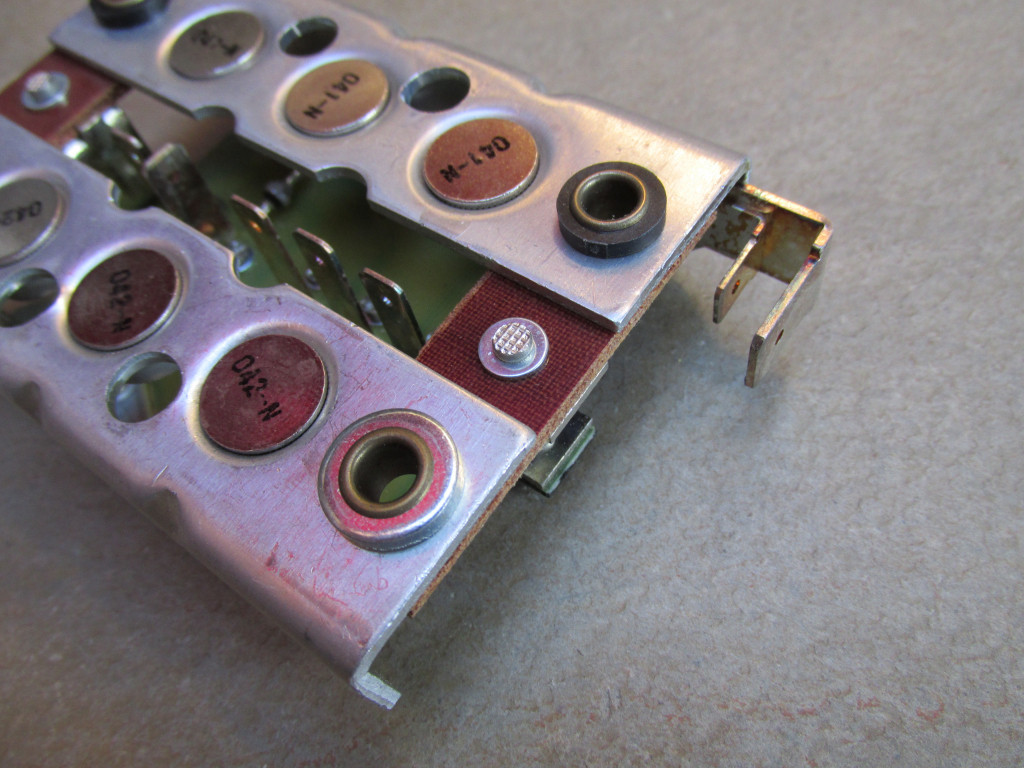
Photo courtesy of Gregory Bender.
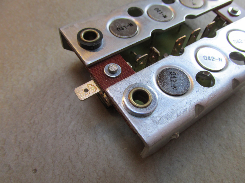
Photo courtesy of Gregory Bender.
V7 Sport rectifier (diode board) electrical connections
The three terminals all in a row on the rectifier
Order amongst these three wires does not matter.
U
terminal - Yellow wireV
terminal - Orange wireW
terminal - Green wire
The remaining terminals on the rectifier
- IF PRESENT
Y
terminal - Blue wire (from alternator) D+
terminal - Red wire (from voltage regulator)61
terminal -- Red wire (to dash indicator light)
- Blue wire with resistor (to fuse box very middle fuse; fused side; fuse will be shared with a gray wire). Optional.
B+
terminal -- Red wire (to fuse box position 1; unfused side)
- Red wire (to front distribution panel position 5; then directly to ignition switch terminal 30/30)
- Mounting bolt - Black wire (to ground)
750 S rectifier (diode board) electrical connections
The three terminals all in a row on the rectifier
Order amongst these three wires does not matter.
U
terminal - Yellow wireV
terminal - Orange wireW
terminal - Green wire
The remaining terminals on the rectifier
- IF PRESENT
Y
terminal - Blue wire (from alternator) D+
terminal - Red wire (from voltage regulator)61
terminal -- Red wire (to dash indicator light)
- Blue wire with resistor (to fuse box very middle fuse; fused side; fuse will be shared with a gray wire). Optional.
B+
terminal -- Red wire (to fuse box position 1; unfused side)
- Red wire (to front distribution panel position 5; then directly to ignition switch terminal 30/30)
- Mounting bolt - Black wire (to ground)
850 T rectifier (diode board) electrical connections
The three terminals all in a row on the rectifier
Order amongst these three wires does not matter.
U
terminal - Yellow wire (from alternator)V
terminal - Yellow wire (from alternator)W
terminal - Yellow wire (from alternator)
The remaining terminals on the rectifier
- IF PRESENT
Y
terminal - Blue wire (from alternator) D+
terminal - Red wire (from voltage regulator)61
terminal -- Blue wire (to dash indicator light)
- Blue wire with resistor (to fuse box position F3; fused side). Optional.
B+
terminal -- Red wire (to battery positive)
- Red wire (to ignition switch)
- Mounting bolt - Black wire (to ground)
750 S3 rectifier (diode board) electrical connections
The three terminals all in a row on the rectifier
Order amongst these three wires does not matter.
U
terminal - Yellow wire (from alternator)V
terminal - Yellow wire (from alternator)W
terminal - Yellow wire (from alternator)
The remaining terminals on the rectifier
Y
terminal - Blue wire (from alternator)D+
terminal - Red wire (from voltage regulator)61
terminal -- Blue wire (to dash indicator light)
- Blue wire with resistor (to fuse box position F3; fused side). Optional.
B+
terminal -- Red wire (to battery positive)
- Red wire (to ignition switch)
- Mounting bolt - Black wire (to ground)
850 T3 rectifier (diode board) electrical connections
The three terminals all in a row on the rectifier
Order amongst these three wires does not matter.
U
terminal - Yellow wire (from alternator)V
terminal - Yellow wire (from alternator)W
terminal - Yellow wire (from alternator)
The remaining terminals on the rectifier
Y
terminal - Blue wire (from alternator)D+
terminal - Red wire (from voltage regulator)61
terminal -- Blue wire (to dash indicator light)
- Blue wire with resistor (to fuse box position F3; fused side). Optional.
B+
terminal -- Red wire (to battery positive)
- Red wire (to ignition switch)
- Mounting bolt - Black wire (to ground)
850 T3 California rectifier (diode board) electrical connections
The three terminals all in a row on the rectifier
Order amongst these three wires does not matter.
U
terminal - Yellow wire (from alternator)V
terminal - Yellow wire (from alternator)W
terminal - Yellow wire (from alternator)
The remaining terminals on the rectifier
Y
terminal - Blue wire (from alternator)D+
terminal - Red wire (from voltage regulator)61
terminal -- Blue wire (to dash indicator light)
- Blue wire with resistor (to fuse box position F3; fused side). Optional.
B+
terminal -- Red wire (to battery positive)
- Red wire (to ignition switch)
- Red wire (to fuse box position F5; unfused side)
- Mounting bolt - Black wire (to ground)
V1000 I-Convert rectifier (diode board) electrical connections
The three terminals all in a row on the rectifier
Order amongst these three wires does not matter.
U
terminal - Yellow wire (from alternator)V
terminal - Yellow wire (from alternator)W
terminal - Yellow wire (from alternator)
The remaining terminals on the rectifier
Y
terminal - Blue wire (from alternator)D+
terminal - Red wire (from voltage regulator)61
terminal -- Blue wire (to dash indicator light)
- Blue wire with resistor (to fuse box position F3; fused side). Optional.
B+
terminal -- Red wire (to battery positive)
- Red wire (to ignition switch)
- Red wire (to fuse box position F5; unfused side)
- Mounting bolt - Black wire (to ground)
V1000 G5 rectifier (diode board) electrical connections
The three terminals all in a row on the rectifier
Order amongst these three wires does not matter.
U
terminal - Yellow wire (from alternator)V
terminal - Yellow wire (from alternator)W
terminal - Yellow wire (from alternator)
The remaining terminals on the rectifier
Y
terminal - Blue wire (from alternator)D+
terminal - Red wire (from voltage regulator)61
terminal -- Blue wire (to dash indicator light)
- Blue wire with resistor (to fuse box position F3; fused side). Optional.
B+
terminal -- Red wire (to battery positive)
- Red wire (to ignition switch)
- Red wire (to fuse box position F5; unfused side)
- Mounting bolt - Black wire (to ground)
1000 SP rectifier (diode board) electrical connections
The three terminals all in a row on the rectifier
Order amongst these three wires does not matter.
U
terminal - Yellow wire (from alternator)V
terminal - Yellow wire (from alternator)W
terminal - Yellow wire (from alternator)
The remaining terminals on the rectifier
Y
terminal - Blue wire (from alternator)D+
terminal - Red wire (from voltage regulator)61
terminal -- Blue wire (to dash indicator light)
- Blue wire with resistor (to fuse box position F3; fused side). Optional.
B+
terminal -- Red wire (to battery positive)
- Red wire (to ignition switch)
- Red wire (to fuse box position F5; unfused side)
- Mounting bolt - Black wire (to ground)
1000 SP II rectifier (diode board) electrical connections
The three terminals all in a row on the rectifier
Order amongst these three wires does not matter.
U
terminal - Yellow wire (from alternator)V
terminal - Yellow wire (from alternator)W
terminal - Yellow wire (from alternator)
The remaining terminals on the rectifier
Y
terminal - Blue wire (from alternator)D+
terminal - Red wire (from voltage regulator)61
terminal -- Blue wire (to dash indicator light)
- Blue wire with resistor (to fuse box position F2; fused side). Optional.
B+
terminal -- Red wire (to battery positive)
- Red wire (to ignition switch)
- Red wire (to fuse box position F5; unfused side)
- Mounting bolt - Black wire (to ground)
850 Le Mans rectifier (diode board) electrical connections
The three terminals all in a row on the rectifier
Order amongst these three wires does not matter.
U
terminal - Yellow wire (from alternator)V
terminal - Yellow wire (from alternator)W
terminal - Yellow wire (from alternator)
The remaining terminals on the rectifier
Y
terminal - Blue wire (from alternator)D+
terminal - Red wire (from voltage regulator)61
terminal -- Blue wire (to dash indicator light)
- Blue wire with resistor (to fuse box position F3; fused side). Optional.
B+
terminal -- Red wire (to battery positive)
- Red wire (to ignition switch)
- Mounting bolt - Black wire (to ground)
Le Mans II rectifier (diode board) electrical connections
The three terminals all in a row on the rectifier
Order amongst these three wires does not matter.
U
terminal - Yellow wire (from alternator)V
terminal - Yellow wire (from alternator)W
terminal - Yellow wire (from alternator)
The remaining terminals on the rectifier
Y
terminal - Blue wire (from alternator)D+
terminal - Red wire *or* white/red (from voltage regulator)61
terminal -- Blue wire (to dash indicator light)
- Blue wire with resistor (to fuse box position F3; fused side). Optional.
B+
terminal -- Red wire (to battery positive)
- Red wire (to ignition switch)
- Red wire (to fuse box position F5; unfused side)
- Mounting bolt - Black wire (to ground)
Le Mans CX 100 rectifier (diode board) electrical connections
The three terminals all in a row on the rectifier
Order amongst these three wires does not matter.
U
terminal - Yellow wire (from alternator)V
terminal - Yellow wire (from alternator)W
terminal - Yellow wire (from alternator)
The remaining terminals on the rectifier
Y
terminal - Blue wire (from alternator)D+
terminal - Red wire (from voltage regulator)61
terminal -- Blue wire (to dash indicator light)
- Blue wire with resistor (to fuse box position F3; fused side). Optional.
B+
terminal -- Red wire (to battery positive)
- Red wire (to ignition switch)
- Red wire (to fuse box position F5; unfused side)
- Mounting bolt - Black wire (to ground)
Le Mans III rectifier (diode board) electrical connections
The three terminals all in a row on the rectifier
Order amongst these three wires does not matter.
U
terminal - Yellow wire (from alternator)V
terminal - Yellow wire (from alternator)W
terminal - Yellow wire (from alternator)
The remaining terminals on the rectifier
Y
terminal - Blue wire (from alternator)D+
terminal - Red wire (from voltage regulator)61
terminal -- Blue wire (to dash indicator light)
- Blue wire with resistor (to fuse box position F3; fused side). Optional.
B+
terminal -- Red wire (to battery positive)
- Red wire (to ignition switch)
- Red wire (to fuse box position F5; unfused side)
- Mounting bolt - Black wire (to ground)
Le Mans 1000 rectifier (diode board) electrical connections
The three terminals all in a row on the rectifier
Order amongst these three wires does not matter.
U
terminal - Yellow wire (from alternator)V
terminal - Yellow wire (from alternator)W
terminal - Yellow wire (from alternator)
The remaining terminals on the rectifier
Y
terminal - Blue wire (from alternator)D+
terminal - Red wire (from voltage regulator)61
terminal -- Blue wire (to dash indicator light)
- Blue wire with resistor (to fuse box position 1; fused side)
B+
terminal - Red wire (to fuse box position 5; unfused side)- Mounting bolt - Black wire (to ground)
California II rectifier (diode board) electrical connections
The three terminals all in a row on the rectifier
Order amongst these three wires does not matter.
U
terminal - Yellow wire (from alternator)V
terminal - Yellow wire (from alternator)W
terminal - Yellow wire (from alternator)
The remaining terminals on the rectifier
Y
terminal - Blue wire (from alternator)D+
terminal - Red wire (from voltage regulator)61
terminal -- Blue wire (to dash indicator light)
- Blue wire with resistor (to fuse box position F4; fused side)
B+
terminal -- Red wire (to battery positive)
- Red wire (to ignition switch)
- Red wire (to fuse box position F5; unfused side)
- Mounting bolt - Black wire (to ground)