Moto Guzzi V700, V7 Special, Ambassador, 850 GT, 850 GT California, Eldorado, and 850 California Police models
Created:
Updated:
A technique using one single-element bulb in each turn signal
My 1971 Moto Guzzi Ambassador didn't come with running lights (the Ambassador didn't come with turn signals originally, either). I'm not a fan of creating new motorcycle laws and I don't think running lights should be made a new motorcycling requirement, but I personally want more visibility both up front and in the rear. I wanted to use my turn signals as combination turn signals and running lights. But, the civilian style turn signals that Moto Guzzi fit to the Eldorado (and offered as a kit for the Ambassador) are only wired for single filament bulbs. Here are the various options I considered:
Replace the pigtails
My first idea was to simply replace the single-wire pigtails with two-wire pigtails. This would allow me to run dual-filament bulbs (1157) instead of single-filament bulbs (1156). I ran into trouble, however, because the two-wire pigtails require a different socket to accept the dual-filament bulbs.
Replace the sockets
My second idea was to replace the single-filament bulb sockets (complete with the pigtails) with dual-filament bulb sockets. However, it is difficult to find sockets that fit easily within the limited space of the turn signals without significant modification to the sockets themselves. Or so I thought...Jason Blasdell found some great sockets that work very well in the Lucas style turn signals used on the older Moto Guzzi (and many other British and Italian) motorcycles. I think he found an excellent solution and I'm pleased to present it here in his own words:
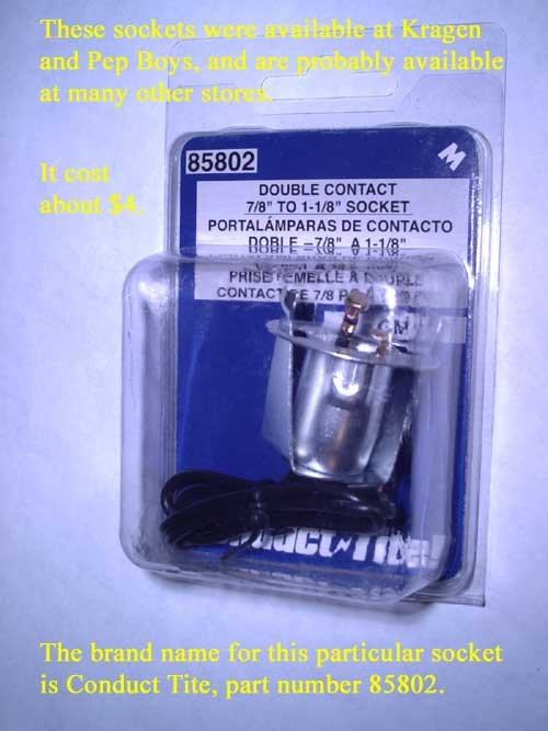
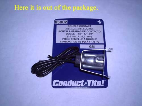
I have found a new solution for the Turn Signals As Running Lights mod. I found some two-conductor sockets that will fit into the turn signal housings. You mentioned it as option 2 on your website. The sockets I came across are very shallow due to a clever spring setup where each conductor gets it's own tiny spring (you can see this on photo 7), as opposed to having one big spring taking up a lot of room inside the socket. The complete conversion is only about USD $4.00 per turn signal, which just accounts for the cost of the socket. I like that it will make the wiring modification terribly easy, since all you will have to do is run one extra wire to each turn signal, and all original functions will continue to work as normal without needing any extra flashers or relays. I will still be adding relays to my bike, though, since I don't like using switches to handle any voltage loads for lighting. I am lucky enough to have two of the left-hand CEV switch boxes (I am installing one on the right instead of the usual one-function switch box), and I don't want to burn one of them up.
Here are some photos that I took while converting my first turn signal to a two-conductor socket. I haven't put voltage on the extra wire yet, but I do have one wire hooked up to the original turn signal lead, and it works fine. One down, three to go. I will wait until my relay mounts arrive before I wire power for the running lights.
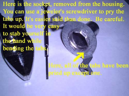
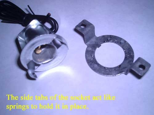
Here is the socket, removed from the housing. You can use a jeweler's screwdriver to pry the tabs up. It's easier said than done. Be careful. It would be very easy to stab yourself in the hand while bending the tabs. Here, all of the tabs have been pried up except one.
Photo courtesy of Jason Blasdell.
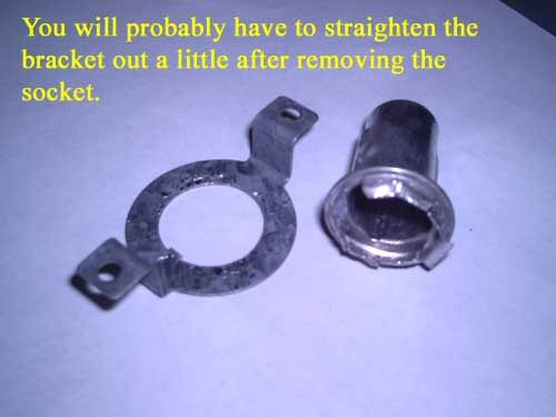
You will probably have to straighten the bracket out a little after removing the socket.
The side tabs of the socket act like springs to hold it in place.
Photo courtesy of Jason Blasdell.
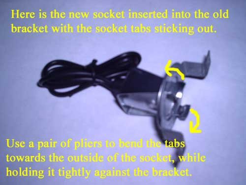
Here is the new socket inserted into the old bracket with the socket tabs sticking out. Use a pair of pliers to bend the tabs towards the outside of the socket, while holding it tightly against the bracket.
Photo courtesy of Jason Blasdell.
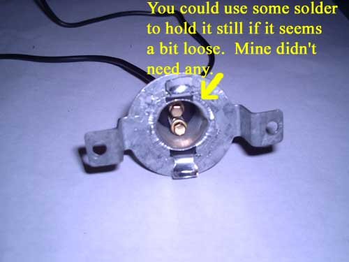
You could use some solder to hold it still if it seems a bit loose. Mine didn't need any.
Photo courtesy of Jason Blasdell.
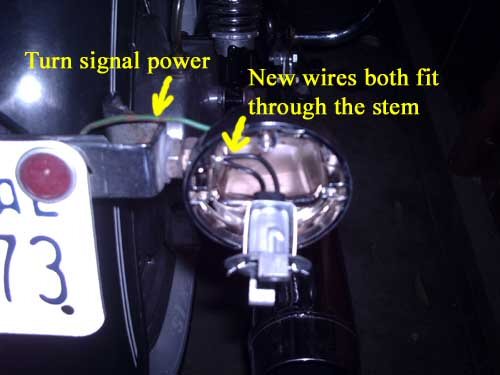
Turn signal power. New wires both fit through the stem.
Photo courtesy of Jason Blasdell.
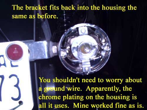
The bracket fits back into the housing the same as before. You shouldn't need to worry about a ground wire. Apparently, the chrome plating on the housing is all it uses. Mine worked fine as is.
Photo courtesy of Jason Blasdell.
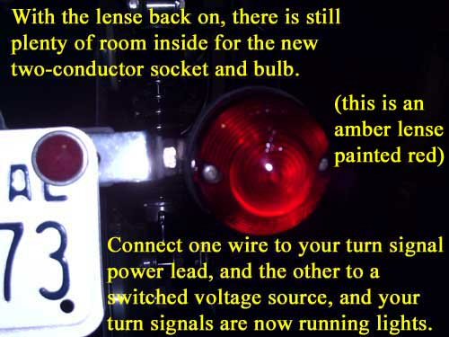
With the lens back on, there is still plenty of room inside for the new two-conductor socket and bulb. This is an amber lens painted red. Connect one wire to your turn signal power lead, and the other to a switched voltage source, and your turn signals are now running lights.
Photo courtesy of Jason Blasdell.
Electronic modification
Some internet research revealed that there are several commercial products readily available to convert existing turn signals into combination turn signals and running lights (e.g., Kriss, SOS Priority Lights, Run-N-Lites). For a number of reasons (cost, inability to work on both the front and rear turn signals, etc.), I decided against these ready-made solutions.
My homemade solution
For a lot less money and a few easily obtainable parts, I created my own DIY solution.
Two flashers. I use Trico (Tridon / Stant) model number EL12. I originally had trouble with these, but cured my problems by adding diodes. Standard thermal flashers work too, but the electronic flashers are flash more regularly and operate more quickly when you thumb the turn signal button. Worth the extra cost, in my opinion.
Two diodes. I use Radio Shack Part Number 276-1661 (6A, 50PIV Rectifier Diodes) or something similar from radio shack. They are cheap and work well. No problems at all. The key thing to keep in mind when selecting diodes is you want them to handle the bulb wattage you'll be using. I use a 23 watt bulb in each turn signal. Which means I've got 46 watts that each diode will need to handle. Depending on how well my charging system is operating (somewhere between 12 and 14 volts is typical), this wattage translates to somewhere between 3 and 4 amps. So, choosing a diode with a 6 amp rating is a safe bet. Don't get bent out of shape if you can't find the exact part number at radio shack...just choose a diode that will handle the bulbs you'll be using in each direction.
Assorted electrical wire and connectors.
How it works
Power from the tail light circuit operates the turn signals as running lights whenever the tail light circuit has power.
When the turn signal switch is activated, the relay diverts the power running directly to the turn signals through the flasher unit. Thus, the turn signals blink.
Turn off the turn signal switch and the relay diverts power away from the flasher.
Download wiring instructions
The following wiring diagrams should provide you with the basic information you'll need to wire your turn signals as combination turn signals and running lights.
Turn signals will only operate if the tail light circuit is hot. This is not a problem on new bikes where the tail light circuit is on with the ignition. But, on older bikes or non-U.S. models, the turn signals may not operate without the tail light switch being turned on.
Using amber colored running lights is legal on the front of any vehicle. However, it is not legal to operate amber colored running lights on the rear. So, you have three choices:
Take your chances with law enforcement.
Only turn the front turn signals into combination turn signals / running lights.
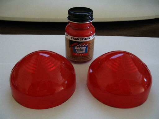
Change the color of the rear turn signals lenses to red by (a) finding and purchasing new lenses or (b) painting your existing lenses with a product such as Testors Transparent Red paint.
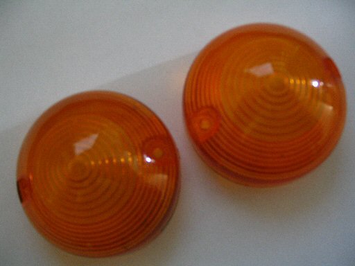
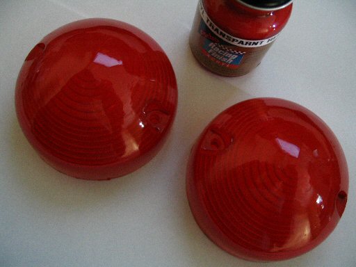
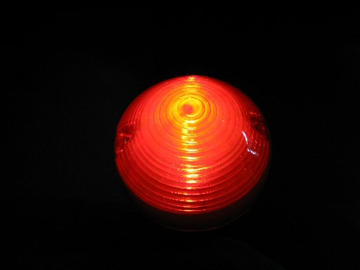
Here are the before and after results with two coats of the translucent red paint. With only one coat, the resulting light was an obvious mix of amber and red. With two coats, however, they look very nice. Not quite as much light is transmitted with the painted red lens when compared to the unpainted amber lens, but the difference is not major and is in line with differences between standard red and amber lenses. Overall, I am very pleased with the results.
Charlie Mullendore of Antietam Classic Cycle fit red LED bulbs into amber lenses. When illuminated, the lenses appear red. Hence, there was no need to paint the lenses.
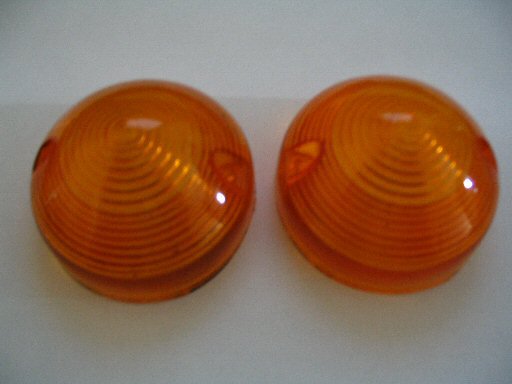
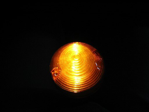
Lenses before transparent paint
Photo courtesy of Gregory Bender.
Photo courtesy of Gregory Bender.
Photo courtesy of Gregory Bender.
Lenses after transparent paint
Photo courtesy of Gregory Bender.
Photo courtesy of Gregory Bender.
Photo courtesy of Gregory Bender.
Gregory Bender's thoughts:
After installing and living with my homemade electronic solution, I now have a very strong preference for modifying the sockets to accept dual filament bulbs. Not only does the modification require less work upfront, but it is also much easier to maintain and doesn't require a location to hide all the electrical wizardry.
A technique using two single-element bulbs in each turn signal
Thanks to Doug Peters for providing the wiring diagram.
Originally intended for use with the lights on Wixom saddlebags, this technique uses resistors and diodes to produce dimmer running lights and brighter brake and turn signal lights.