Starter and solenoid repair (Bosch)
Moto Guzzi V700, V7 Special, Ambassador, 850 GT, 850 GT California, Eldorado, and 850 California Police models
I've been meaning to rebuild a couple starters and solenoids I've had for quite some time now. One functioned perfectly but needed cosmetic improvement. That is the starter you'll see pictured below. The solenoid on the other starter functioned fine, but the starter did not turn. Cleaning up the commutator solved that problem.
- Always start with a spotless work area!
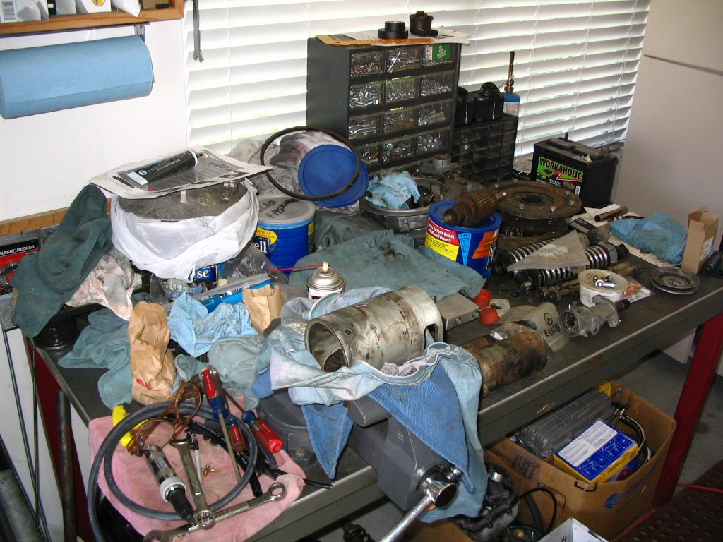
Photo courtesy of Gregory Bender.
- OK, that's much better :> Here is the crusty specimen. Time to get started.
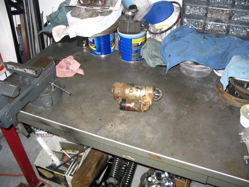
Photo courtesy of Gregory Bender.
- First, remove the wire connecting the starter to the solenoid.
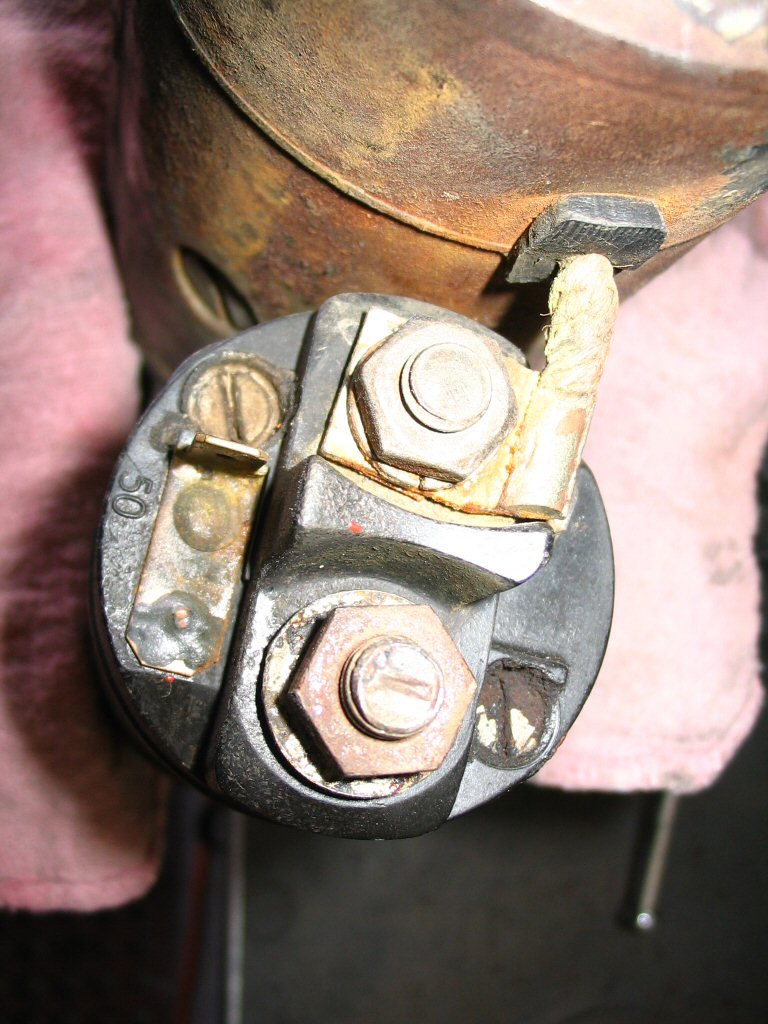
Photo courtesy of Gregory Bender.
- When you are reassembling, you can reference the terminals so you make sure you align the proper terminal on the solenoid.
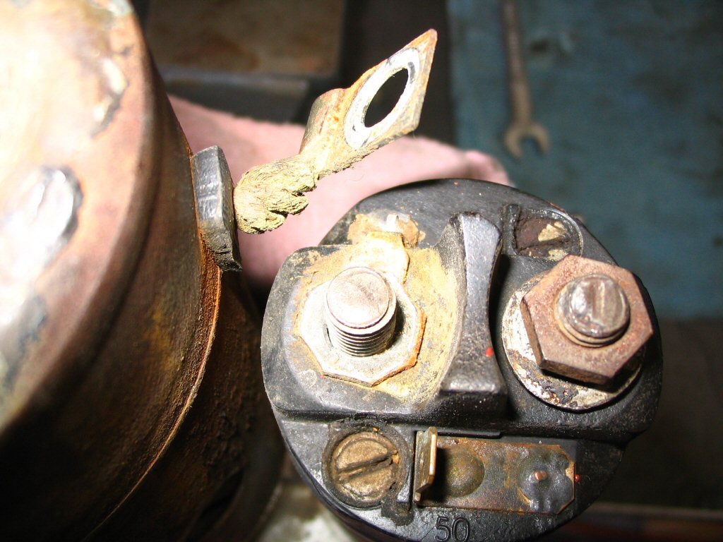
Photo courtesy of Gregory Bender.
- Now remove the screws the secure the solenoid to the starter.
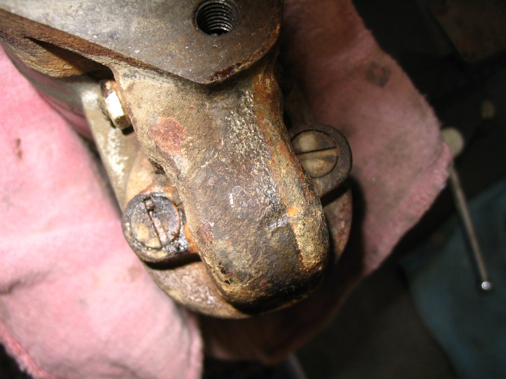
Photo courtesy of Gregory Bender.
- This is what they look like. The wetness is from PB Blaster...expect to soak these and use an impact driver (the kind with a hammer) to get them unstuck. Upon reassembly, be sure to use medium strength thread locking compound on these screws. If you don't, you run the real risk of them loosening up and falling out.
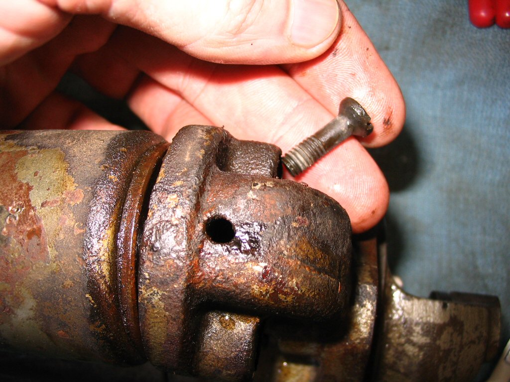
Photo courtesy of Gregory Bender.
- Remove the solenoid from the starter. Note how the hole in the solenoid's arm fits around the lever.
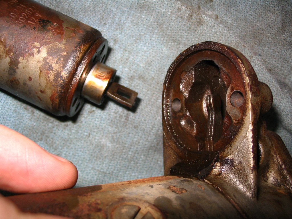
Photo courtesy of Gregory Bender.
- Here is a close up picture of the solenoid arm and plunger. I screwed the screws back in a few threads so I wouldn't lose them.
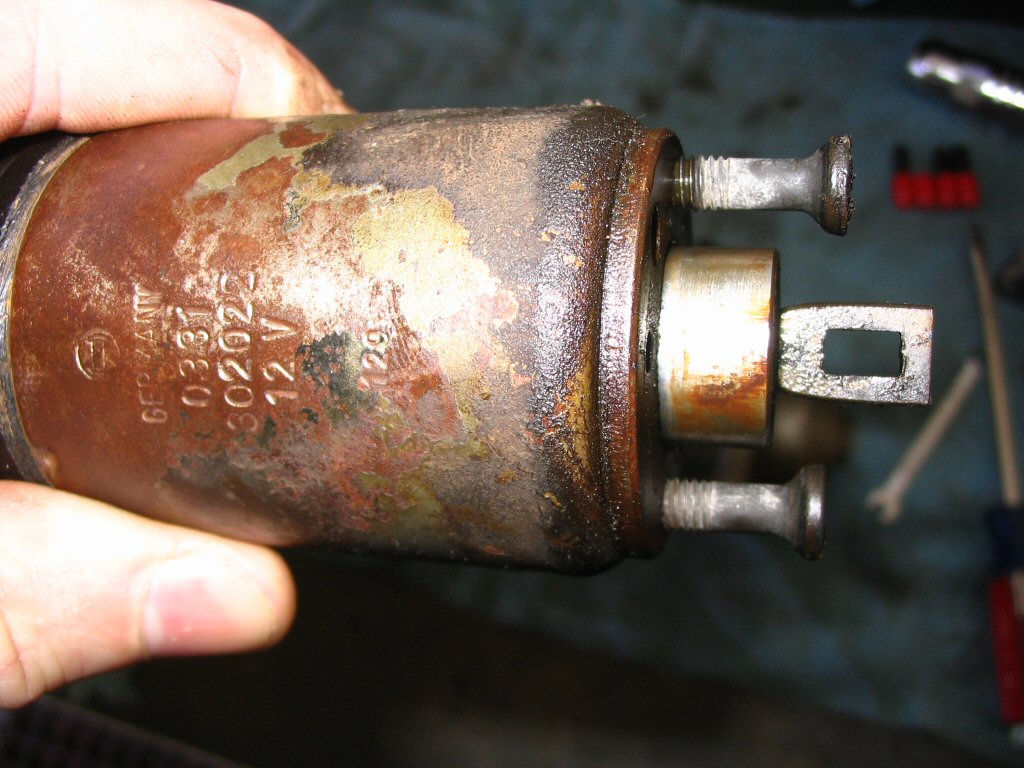
Photo courtesy of Gregory Bender.
- This nut secures the bolt that acts as a pivot for the arm that engages and disengages the bendix with the ring gear. You should be able to move the arm back and forth and watch the bendix (starter gear) slide back and forth.
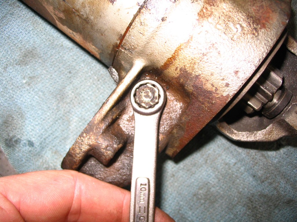
Photo courtesy of Gregory Bender.
- Remove the nut and bolt. You won't be able to withdraw the arm just yet.
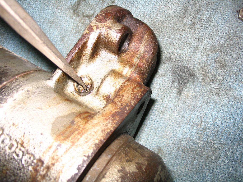
Photo courtesy of Gregory Bender.
- Next, remove the screws that secure the small rear cover.
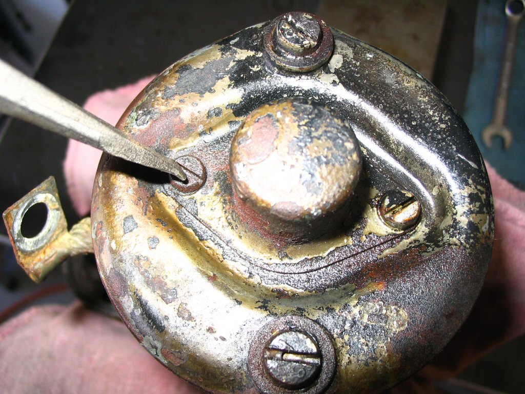
Photo courtesy of Gregory Bender.
- Pull it off and this is what you'll see.
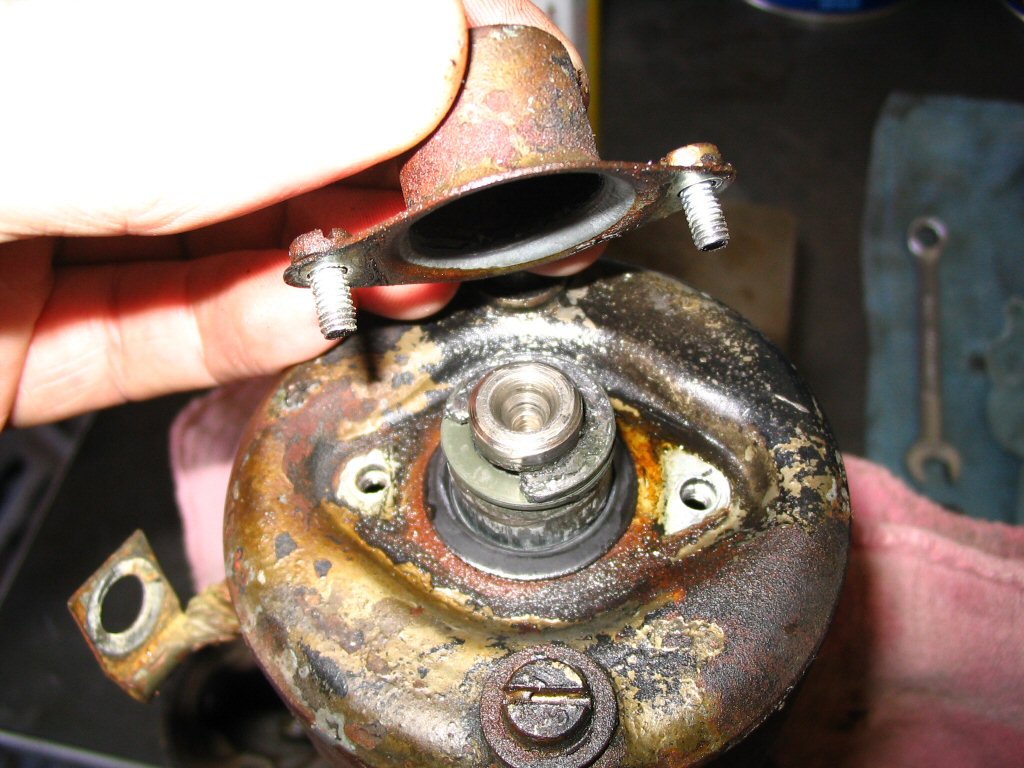
Photo courtesy of Gregory Bender.
- Withdraw the
U
shaped retainer from its slot.
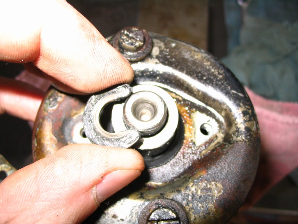
Photo courtesy of Gregory Bender.
- Withdraw the shimming washer.
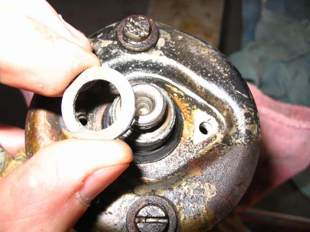
Photo courtesy of Gregory Bender.
- I first thought this was just one washer. But while I was cleaning everything up, I found it was actually a stack of 3 washers stuck together: 1 thick and 2 thin.
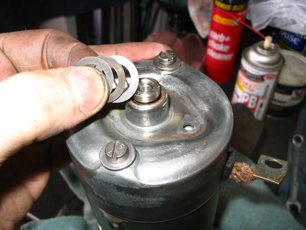
Photo courtesy of Gregory Bender.
- Remove the rubber seal.
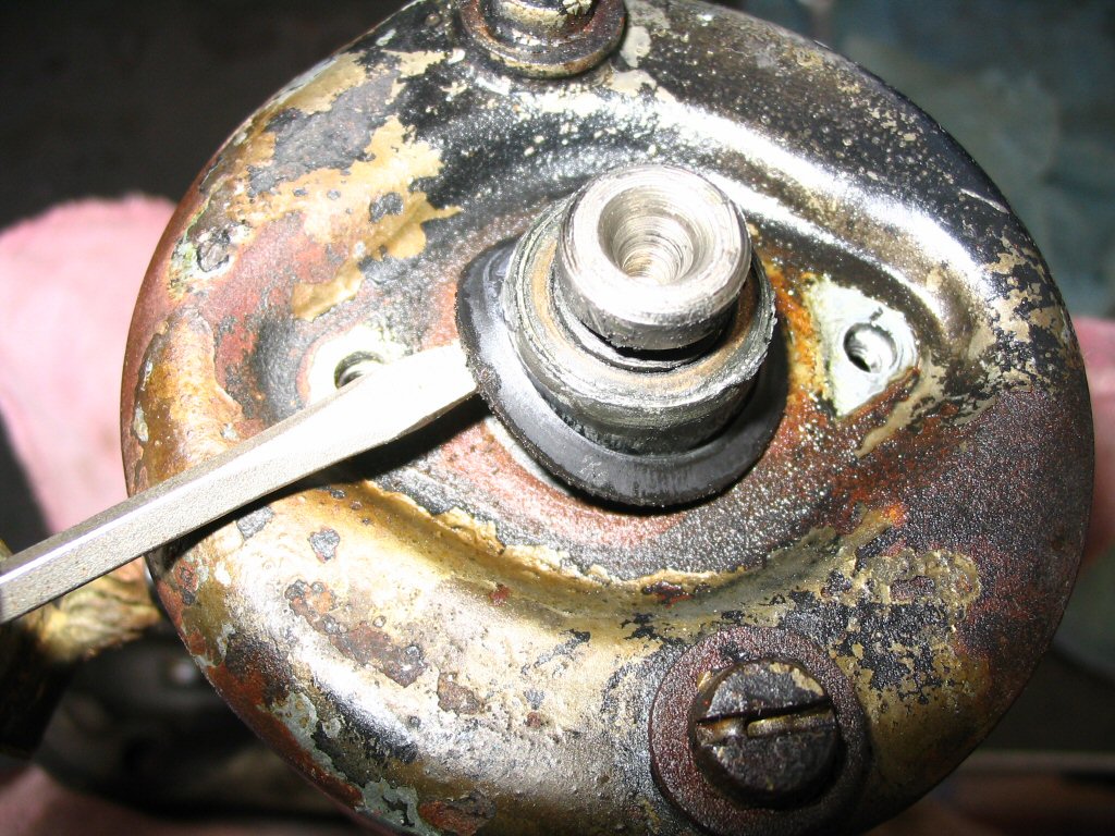
Photo courtesy of Gregory Bender.
- Now remove the big screws. PB Blaster is your friend.
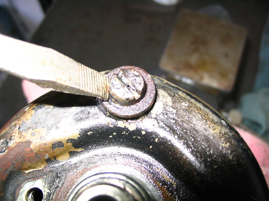
Photo courtesy of Gregory Bender.
- With the big screws removed, you can pry off the big end cap. Just a twist with a small screw driver is all mine needed.
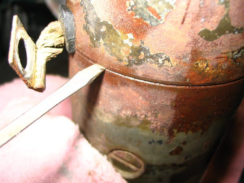
Photo courtesy of Gregory Bender.
- Wiggle it off. It only fits one way.
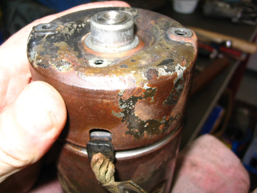
Photo courtesy of Gregory Bender.
- Here is what is inside.
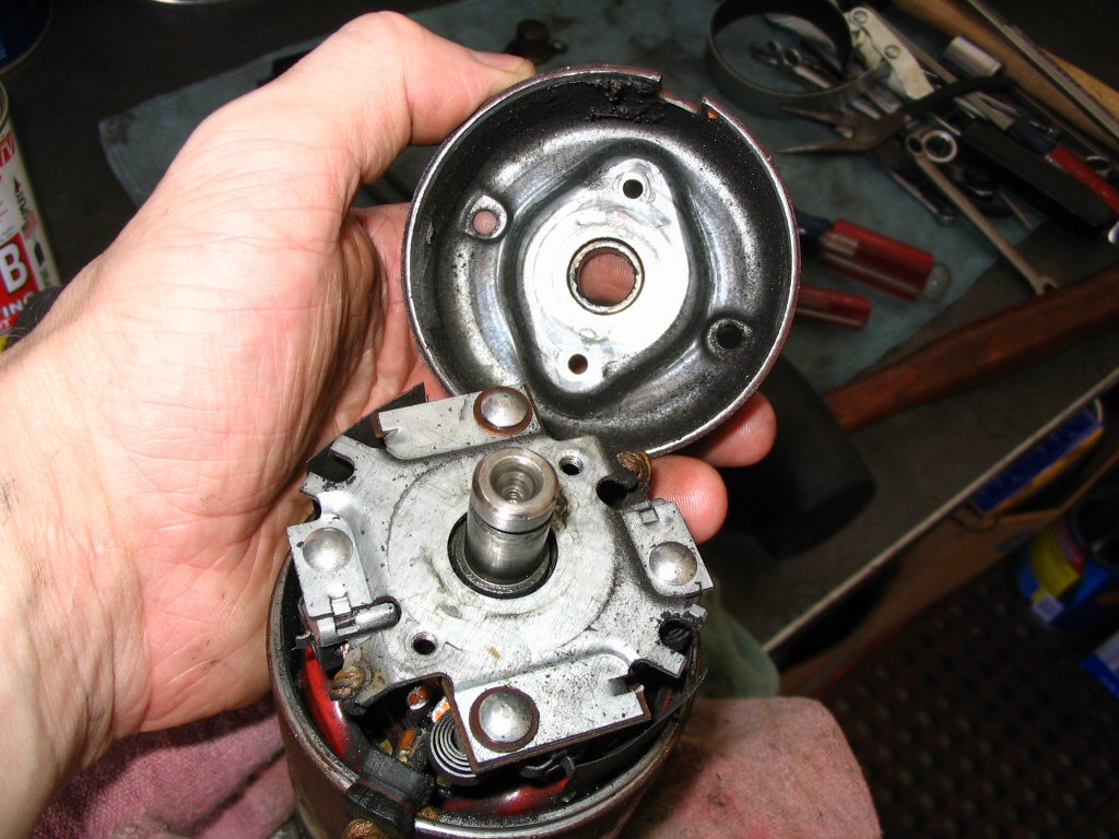
Photo courtesy of Gregory Bender.
- Here are all the parts for the top in the order in which to reassemble them.
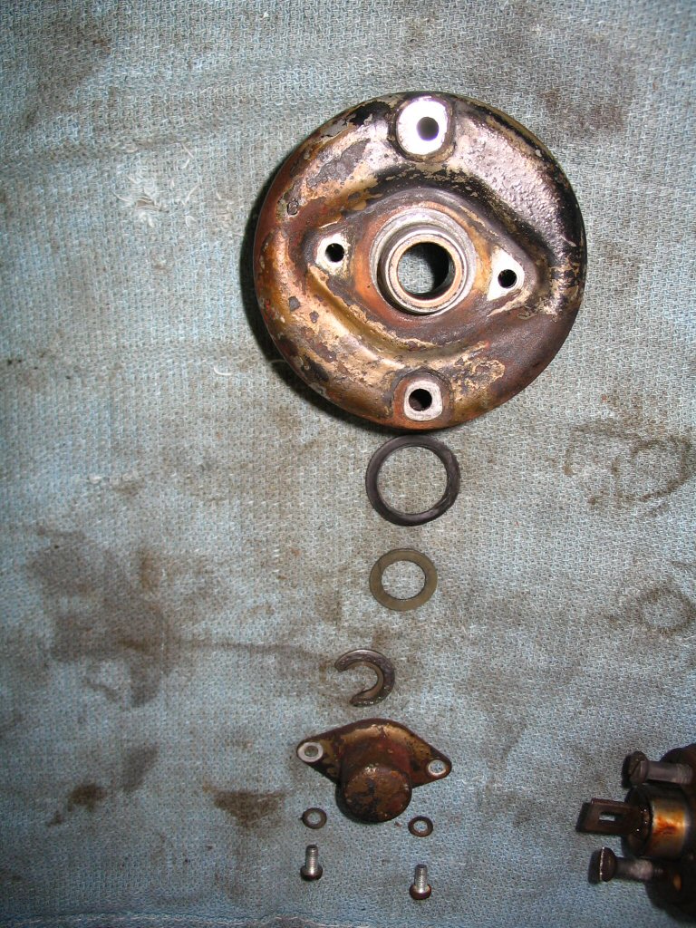
Photo courtesy of Gregory Bender.
- There are 4 brushes total. 2 are secured to the brush plate and need not be removed. The remaining 2 are soldered to the field coils and must be removed. Just pry the spring back and pull the brush out.
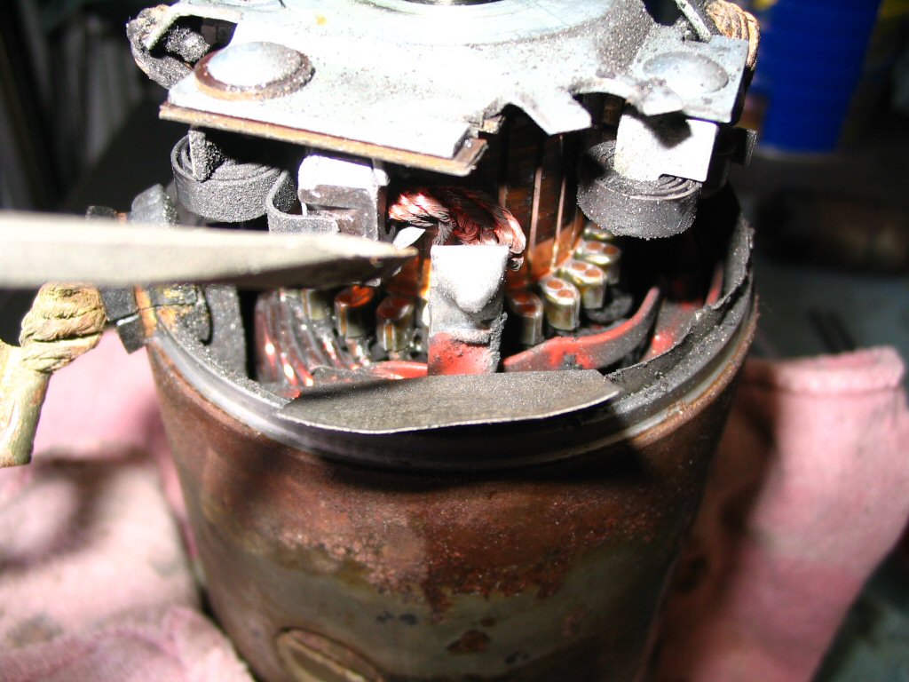
Photo courtesy of Gregory Bender.
- Here the brush is removed.
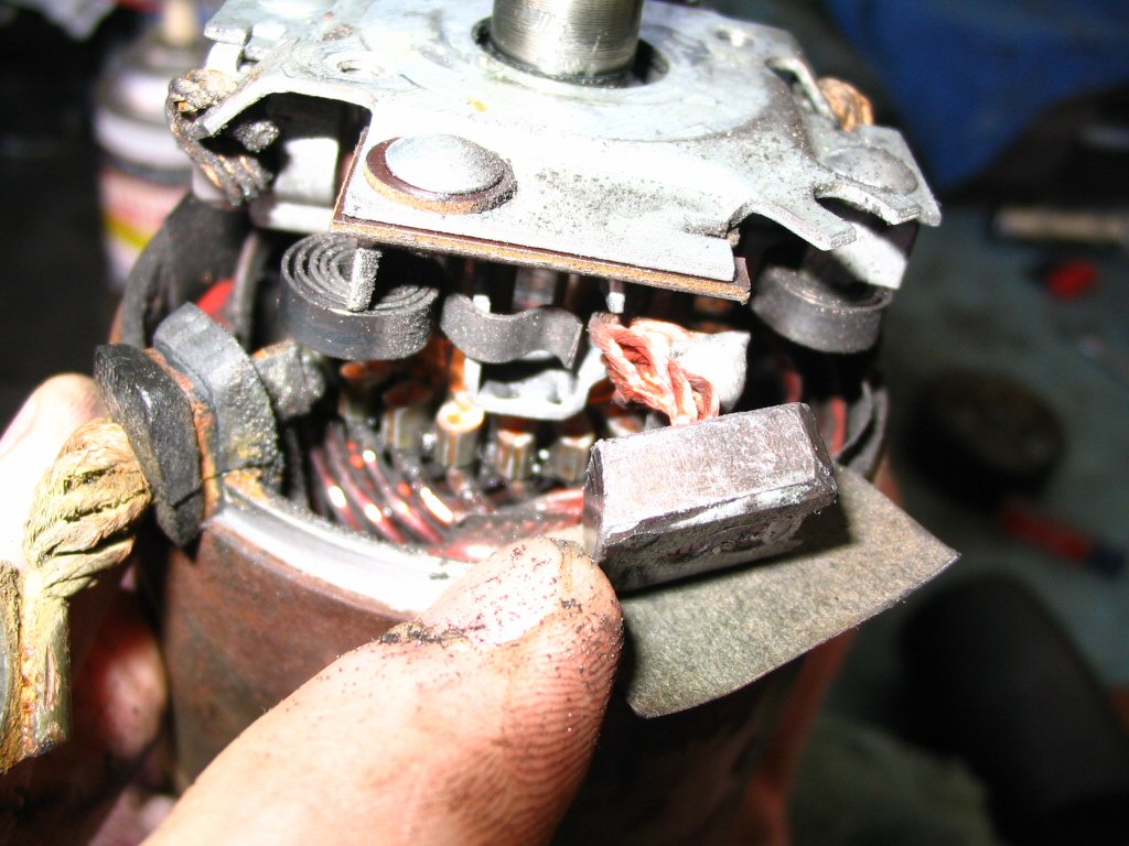
Photo courtesy of Gregory Bender.
- Now the brush holder just slides off...you can get a better view of 2 brushes that are attached to the field coils.
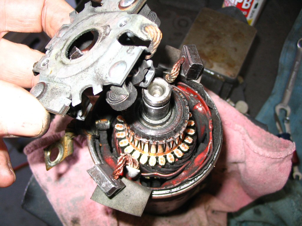
Photo courtesy of Gregory Bender.
- Here is a view of the brush holder from the underside. It doesn't matter how it goes back on as the connections are identical.
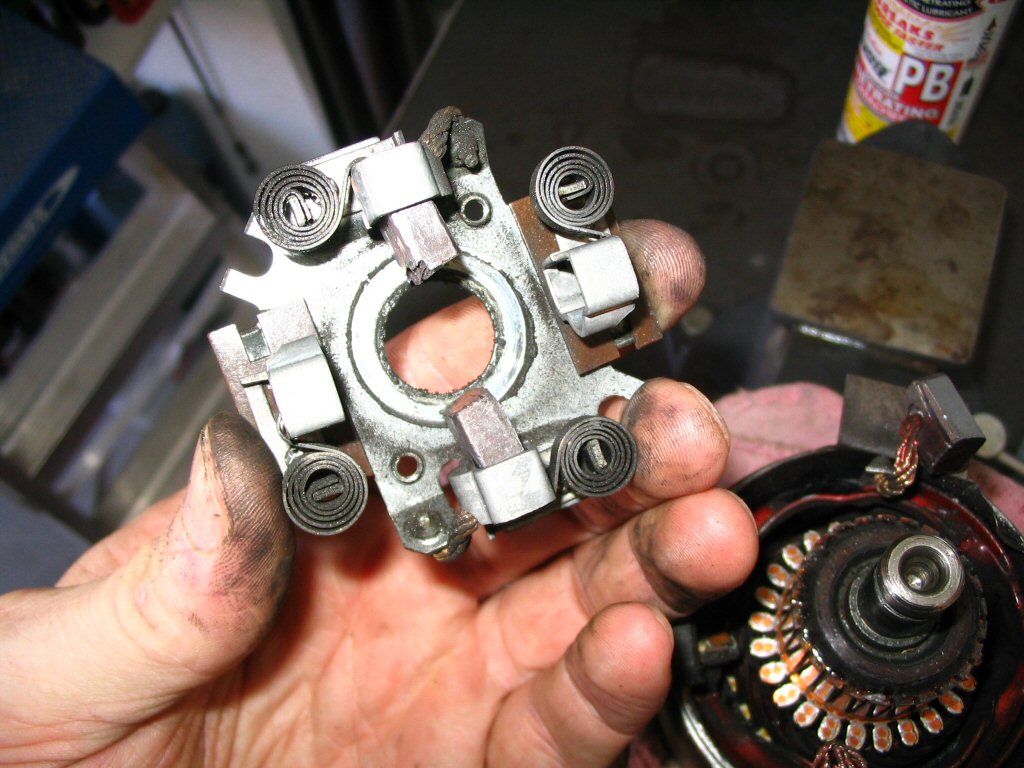
Photo courtesy of Gregory Bender.
- Now you can pull the main body off.
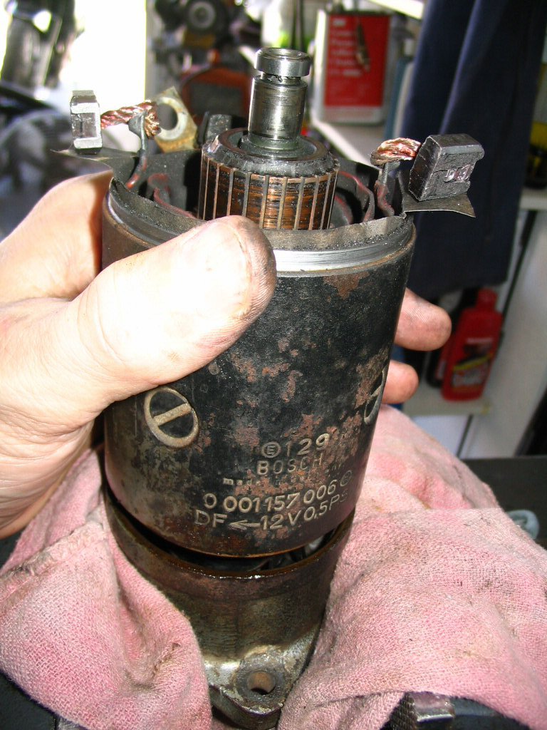
Photo courtesy of Gregory Bender.
- Here it is removed. It only goes back on one way...I didn't get a picture of it, but there is a relief for the little rubber piece that fits between the starter and solenoid.
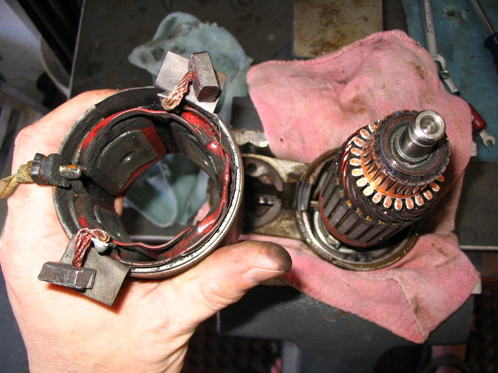
Photo courtesy of Gregory Bender.
- Now you can withdraw the winding. It comes right out and may bring the engagement arm along with it.
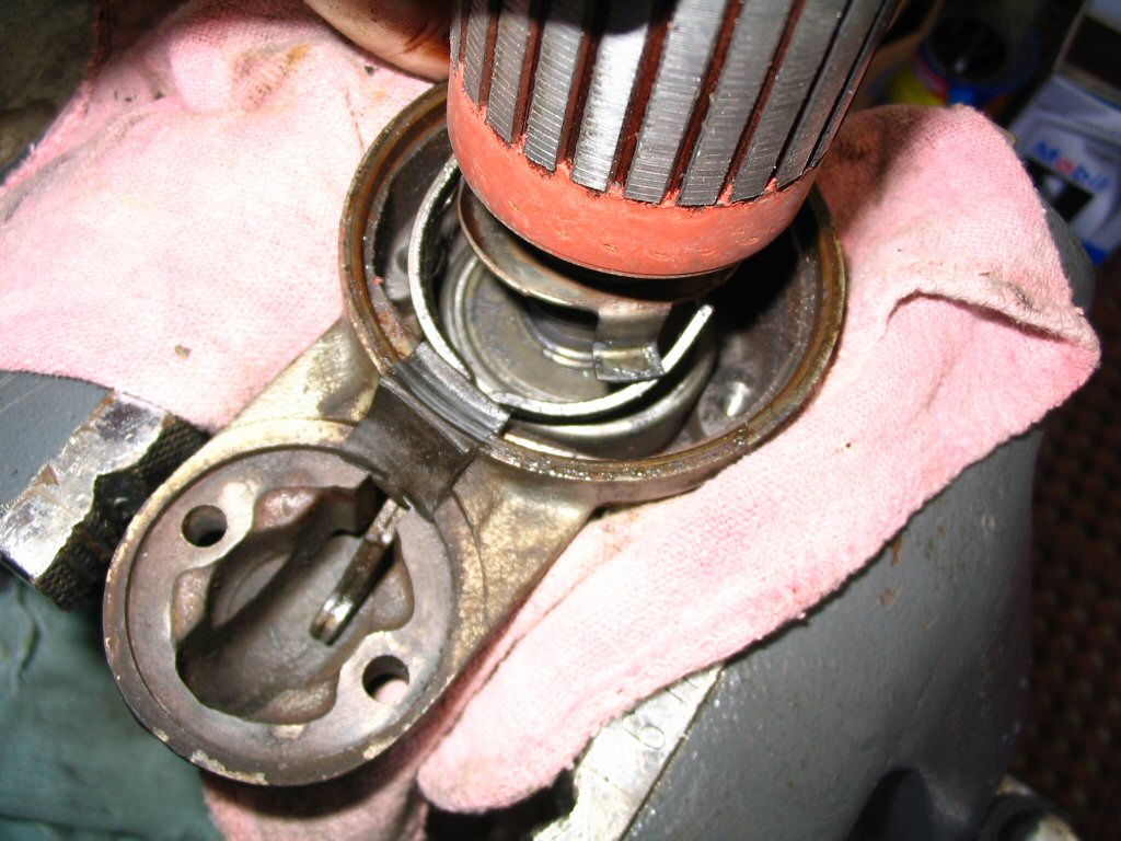
Photo courtesy of Gregory Bender.
- Here is how the engagement arm is supposed to engage the bendix. It is reversible so don't worry about right side up or anything like that.
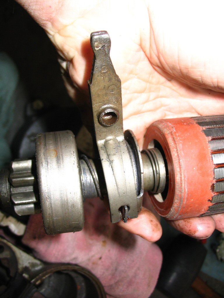
Photo courtesy of Gregory Bender.
- Here is that little rubber piece that fits between the starter and solenoid holes. Pluck it right out.
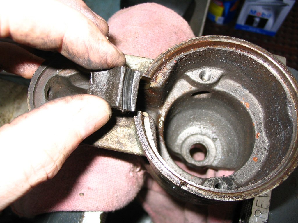
Photo courtesy of Gregory Bender.
- To remove the bendix, use a 13 mm 1⁄4 inch drive deep-well socket to drive the steel collar down off of the wire ring. Tap the socket with a hammer.
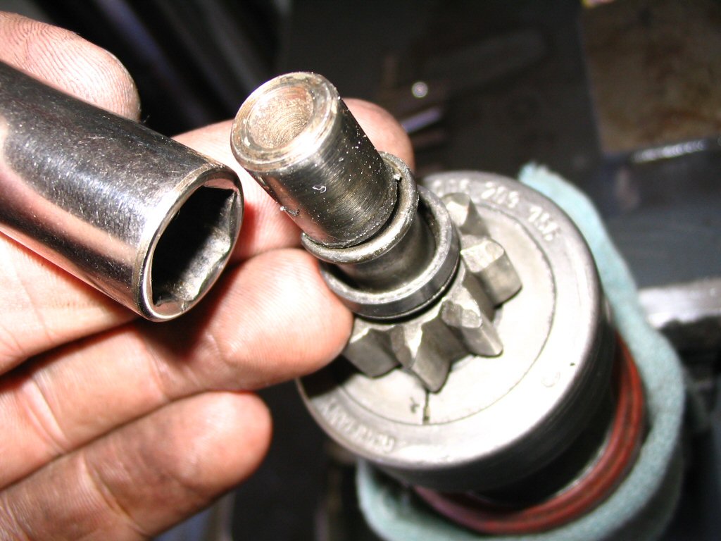
Photo courtesy of Gregory Bender.
- Now pry off the wire ring.
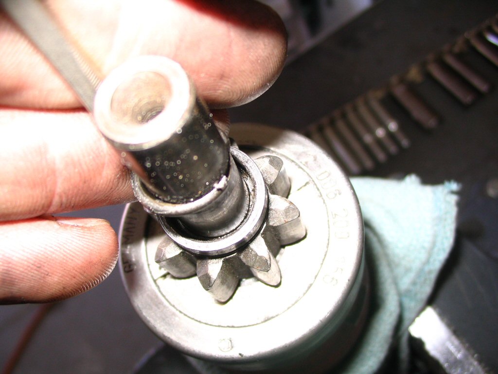
Photo courtesy of Gregory Bender.
- And here is the bendix. I pulled it off as an exercise to see if I could do it, but I wouldn't bother with it unless it was suspect. It is very difficult to get the steel collar back around the ring. I spent more time doing that than anything else. It finally worked after I spent a lot of time bending the wire ring with a pliers to get it very close to the size of the recess. Doable but not fun.
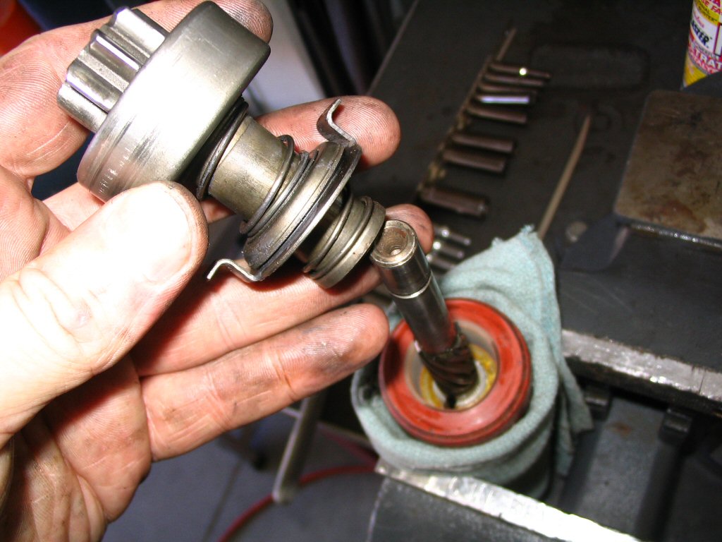
Photo courtesy of Gregory Bender.
Thanks to Steve Hilhorst for sending me some excellent tips for removing and installing the bendix. In Steve's own words:
I used to have some special tools that I had manufactured to assist in the job, but it can be done with normal tools.
When I was in the trade I made a hollow punch from a piece of pipe. The ID of the punch was just bigger than the armature shaft, and the OD of the punch was just smaller than the ID of the retaining collar. I had many different punches I had made to work on starter motors with different diameter armatures.
I see under the heading starter and solenoid repair (Bosch) at step 33 you had trouble getting the retaining circlip back into its collar.
Here is the trade tip that will make you think
why didn't I think of that
. Works for any brand starter.I have not got photo's, but I will try to explain as as best I can.
Firstly place the armature in a bench vice, horizontally with the drive end of the starter facing to the right. Snug it up firm in the vice as you don't want it to move, but you don't want to squash it either. best to use soft alloy vice jaws, or alloy angle as same to avoid damage.
The trick is to get the circlip back into shape as best as possible with pliers, getting it smaller than the armature shaft is ideal. You place the pinion (or bendix) on the shaft, and then the retaining collar. Then place the smaller than the shaft circlip on the end of the shaft and get a piece of soft timber (pine works well) and place this against the circlip. Get a hammer and one quick hit and the circlip is now on the shaft, although still 15 mm or so from being in the groove. This is where I used the previously mentioned punch - Slide the circlip up the shaft until it pops into the groove. If you havn't got a punch the right size you may be able to use a socket, or even a pair of pliers to push the circlip on until it falls into it's groove. After doing this be sure to check the surface of the shaft that runs in the front bush. If it has been scratched by the circlip while being pushed on, a quick polish by hand with abrasive paper will restore the finish of the shaft.
Now for the retaining collar. Get a Stillson wrench [pipe wrench in USA parlance], the bigger the better, I have found that 18 inch works well. With practice this can be done on your own, but some may find it easier with two people. (If you don't have a Stillson wrench you could use vise grips, but you will definately need two people to get the job done.)
You will notice that the spline that the pinion runs on is twisted. Twist the pinion outwards (towards the front of the armature) until the pinion rests on the retaining collar. You will notice that the pinion gear has a one way clutch in it. Spin it one way and it free wheels, spin it the other and it tries to spin the armature shaft in the vice. Place the Stillsons on the teeth of the pinion so that it is trying to spin the armature. If you place the handle of the Stillsons slightly above parallel to the ground then the weight of the Stillsons will hold the pinion against the collar on its own.
At this point the only thing stopping the collar from popping into position is the circlip which needs to be compressed into its groove to fit properly. If you have a sloppy circlip sometimes just a bit of pressure in the handle of the Stillsons will be enough to pop the collar over the circlip, but mostly more help is needed.
Once again this is where I would use my special punch. Slide it over the shaft up onto the circlip, and while holding a bit of pressure against the handle of the Stillsons just give the punch a tap with a hammer and the circlip will compress into its groove allowing the collar to pop into place...job done. If you don't have the special punch the same can be dome with a small flat screwdriver, you just have to hold constant pressure on the handle of the Stillsons while tapping the screwdriver with a hammer on a few spots of the circlip until it pops in.
If you have the right tools this procedure should take about 10 seconds to complete.
Thanks to Allan Michell for sending me some tips and photos related to installing the bendix. In Allan's own words:
The refitting of the circlip is very easy.I can provide more pictures and details if you are interested.
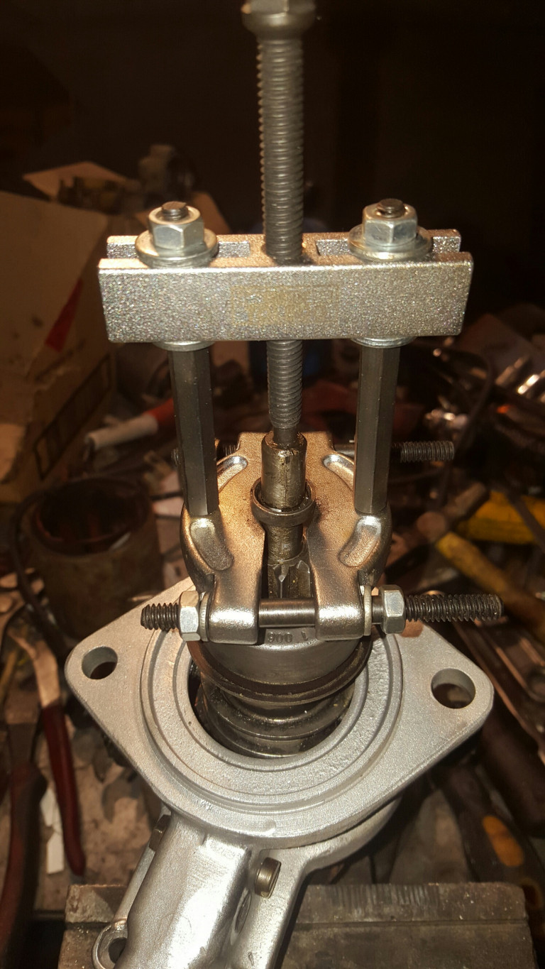
Replacing the circlip that prevents the bendix from extended too far. Photo courtesy of Allan Michell.
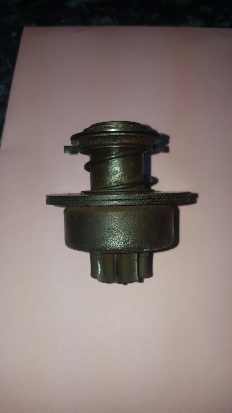
Bendix. Photo courtesy of Allan Michell.
- And here are the 3 pieces.
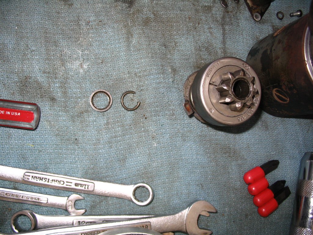
Photo courtesy of Gregory Bender.
- The winding. No need to drive the shaft out...I'm not that curious! That is it for the starter...from here you can clean up the commutator (the part that the brushes run on) with some fine sandpaper. You can also replace the brushes with new ones. Just a bit of soldering will take care of that. I gave everything a bath in some degreaser and then used my wire wheel to clean up the nasty exterior bits.
Thanks to Allan Michell for sending me some tips and photos related to the commutator. In Allan's own words:
The armature should be machined and undercut because it will not be round.
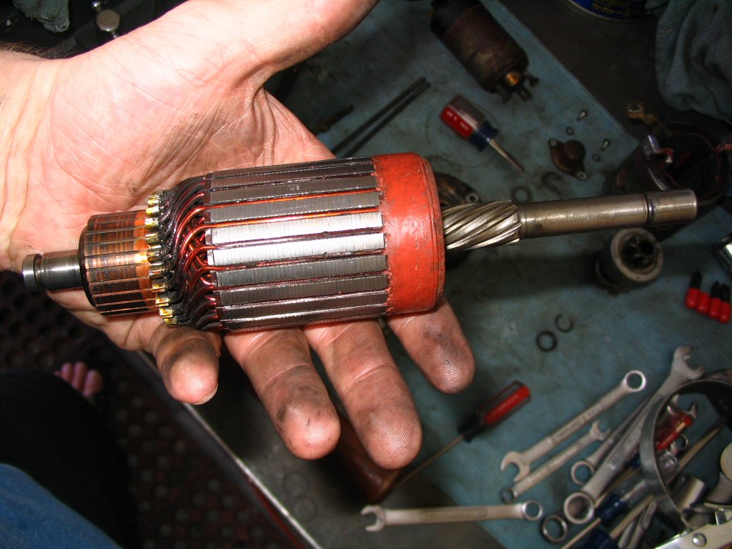
Photo courtesy of Gregory Bender.
- Alright, onto the solenoid. Remove the 2 screws that secure the cap. They may be covered in some silicon glue that you'll have to dig out first.
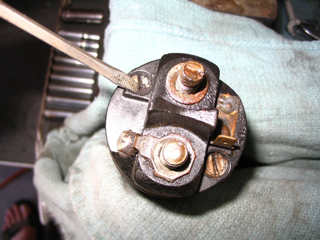
Photo courtesy of Gregory Bender.
- Here are the screws.
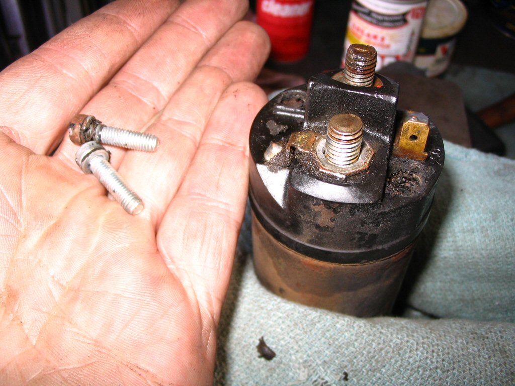
Photo courtesy of Gregory Bender.
- Now heat up the connections with a soldering iron. Once the solder has liquefied, pull upward on the cap with your hand. Then do the other side. Move back and forth until the cap comes free.
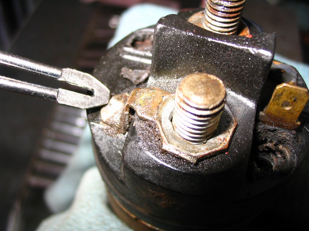
Photo courtesy of Gregory Bender.
- Here is the cap as it was removed.
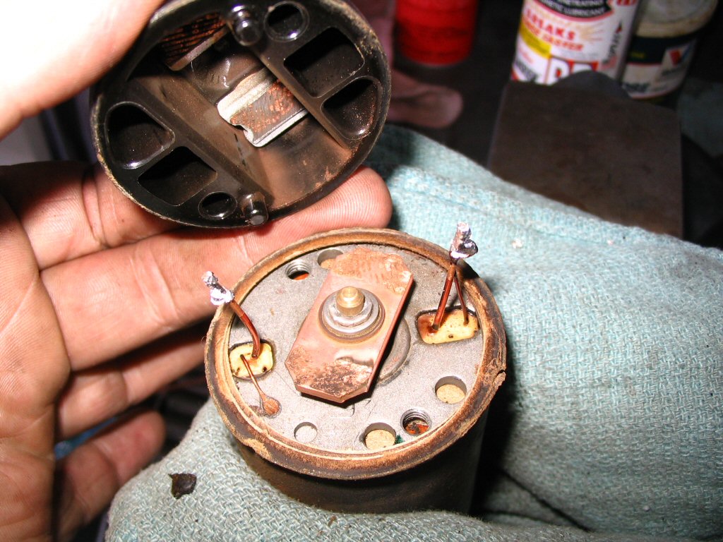
Photo courtesy of Gregory Bender.
- A look at the contacts inside the cap. Clean these up well. I like to use a tiny wire wheel on my Dremel tool. Then remove any residue with a cleaner (like rubbing alcohol or carb cleaner or such).
Thanks to Allan Michell for sending me some tips related to the contacts. In Allan's own words:
You either replace the contacts and cap for a new copper sliding contact, or turn it over. You can also remove the studs, machine them, and refit.
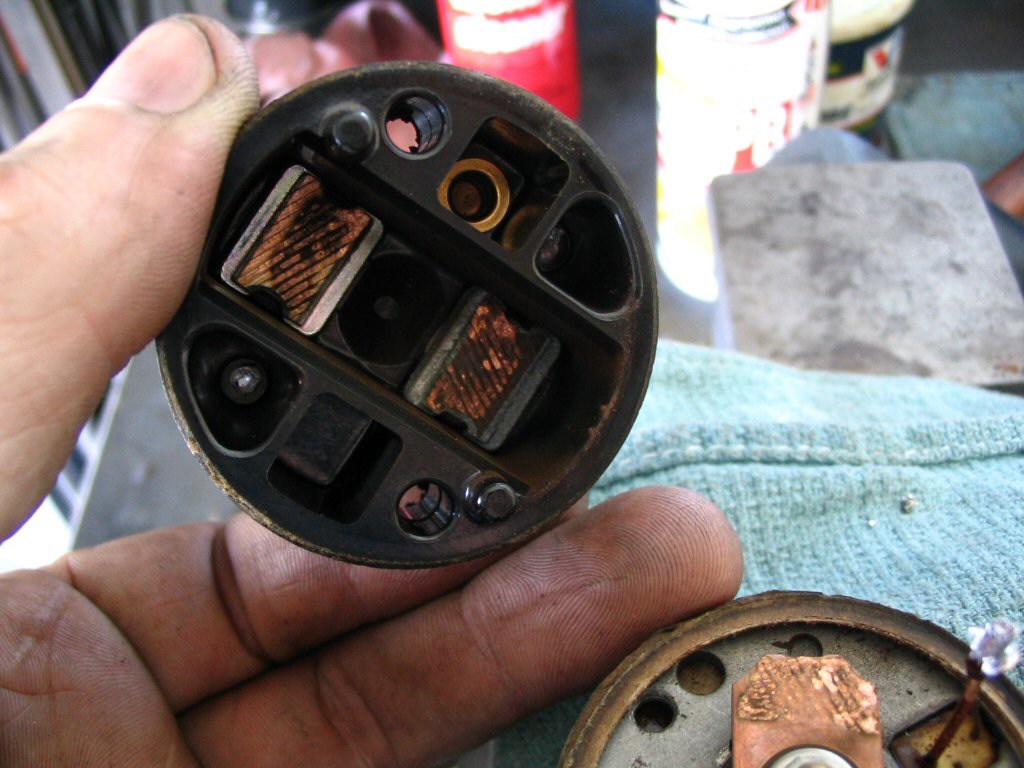
Photo courtesy of Gregory Bender.
- Here is how the cap goes back on. The side that has two wires angling up goes to the terminal on the cap with the spade connector. Don't get this wrong or you'll have to swap it back around.
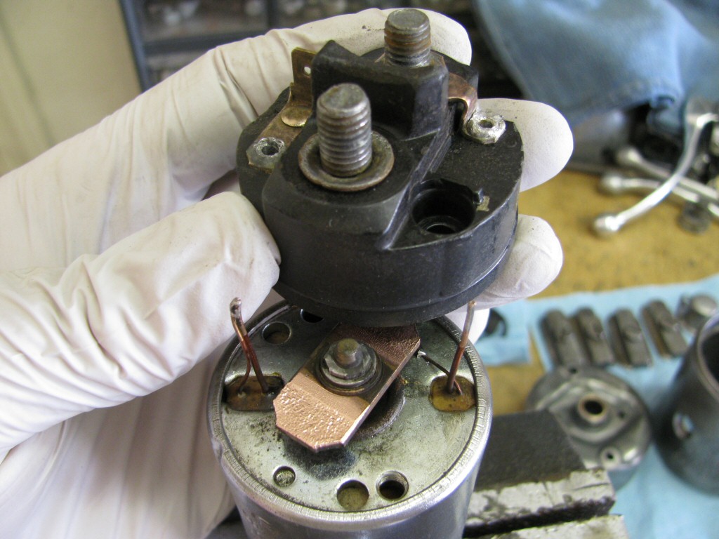
Photo courtesy of Gregory Bender.
- Carefully remove the first cardboard shim.
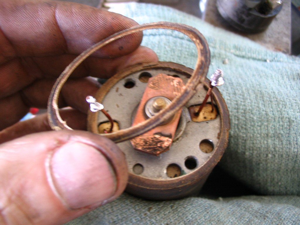
Photo courtesy of Gregory Bender.
- Carefully remove the second cardboard shim. Yes, I found two of these on mine. Combined thickness was 1.5 mm or 0.06 inch. Be very careful with these and do not lose or destroy them. The thickness they provide is critical. If they are totally destroyed, replace them with shims of identical thickness.
Thanks to Allan Michell for sending me some information on these shims/washer. In Allan's own words:
I actually dismantle the drives clean repair them need theese washers 55 mm OD 34 mm ID about 2 mm thick.
Made of fibre or plastic.
Used on Mercedes and VW Bosch starters.
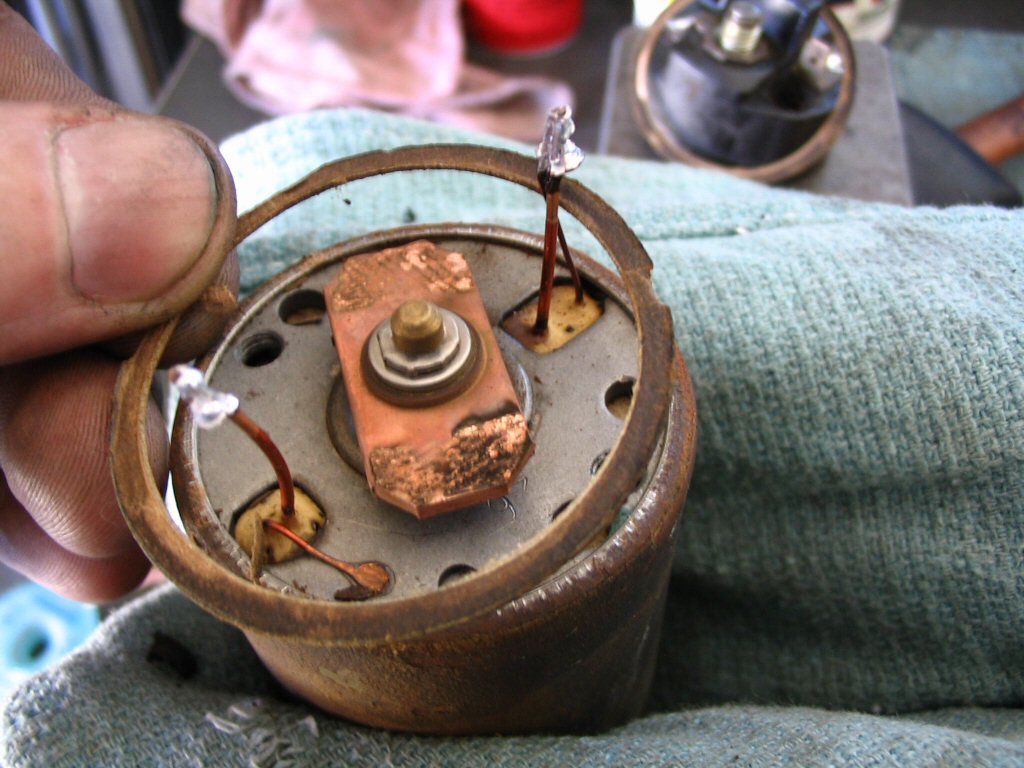
Photo courtesy of Gregory Bender.
- As usual, assembly is the reverse of disassembly. Be sure to use anti-seize on all of the threads EXCEPT for the bolts that secure the solenoid to the starter body...use medium strength thread locking compound on those. Put some grease on the bushings and on the shaft where the bendix slides.
Here is the finished starter and solenoid reassembled and painted. I painted the starter with black truck bed liner in a spray can (thanks to Mark Etheridge of Moto Guzzi Classics for that tip) and I primed and painted the solenoid body with gloss black paint. Stainless steel washers and nuts at the rear of the solenoid complete the project. All in all, I was able to rebuild two starters/solenoids in about four hours of time one humid Florida Saturday afternoon in August, 2006.
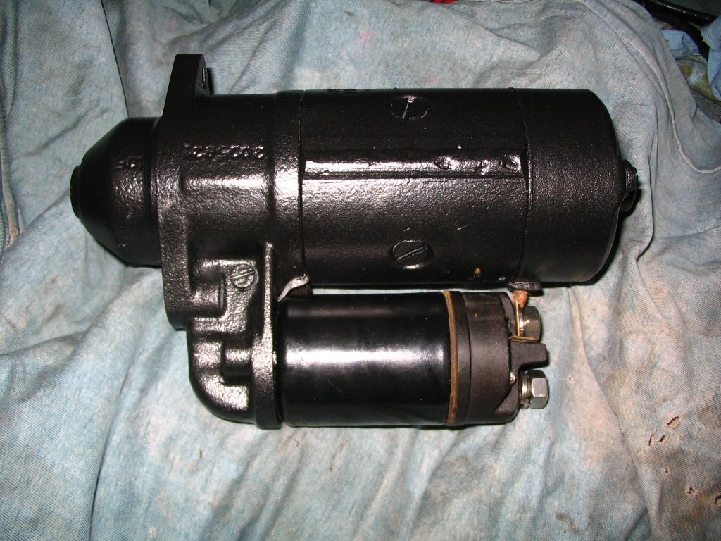
Photo courtesy of Gregory Bender.