Moto Guzzi V700, V7 Special, Ambassador, 850 GT, 850 GT California, Eldorado, and 850 California Police models
Created:
Updated:
This is a series of photos I took during the assembly of the carburetors on my V1000 I-Convert project bike. These are Dellorto VHB 30 carburetors. But, the procedure is 100% identical for Dellorto VHB 29 carburetors. Thanks to Charlie Mullendore of Antietam Classic Cycle, Robert Hawkes, Steve Farris, Adam S., Joe Tokarz, and Ken Chicken for making helpful suggestions for improvement.
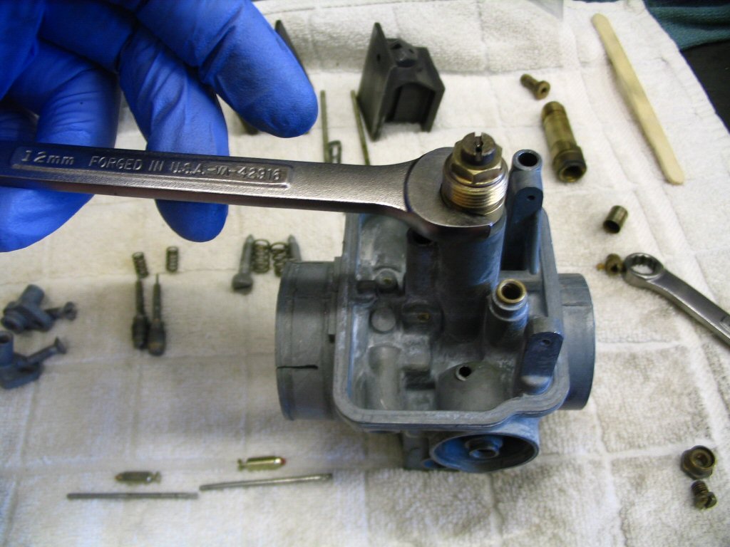
It is a very good idea to work on one carburetor at a time. That way, you can refer to the assembled carburetor as a pattern.
(2) Float needles (these are cheap enough that I always have them on hand)
(2) Floats (I order these if I need them. I do not replace unless I detect leaks in the originals.)
Disassembly
Disassembly is pretty much the reversal of assembly. So, just start from the last photo, and work your way up to the top.
Cleaning
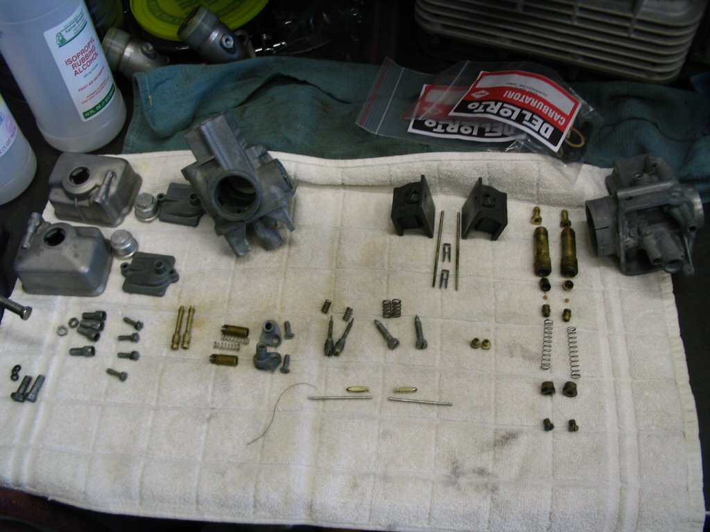
Prior to these photos being taken, I had completely disassembled both carburetors and soaked all of the metal parts in a bucket of carb cleaner. With the parts out of the carb cleaner, I thoroughly rinsed them in a bucket of rubbing alcohol. Rubbing alcohol dries very quickly, leaves no residue, and - in my experience - does a good job of neutralizing the carb cleaner (though I'm not a chemist and haven't a clue whether or not alcohol neutralizes the carb cleaner, or simply dilutes it to a point where it doesn't matter). Use gasoline if you like, but I prefer rubbing alcohol. Even after cleaning, some of the brass parts appear discolored. Not to worry, they are clean and the discoloration really doesn't matter, as they will discolor again soon enough. But, if you like, a quick turn at a fine wire wheel (not coarse or heavy) will polish them up nicely. Just be cautious around the openings so that they are not enlarged and DO NOT WIRE WHEEL THE TAPERED NEEDLE AT ALL.
As an alternative, after soaking the parts in carburetor cleaner, Charlie Mullendore of Antietam Classic Cycle rinses them thoroughly in cold water, then hot water, and finally sprays through all of the passages with Berkebile 2+2 Gum Cutter.
Assembly
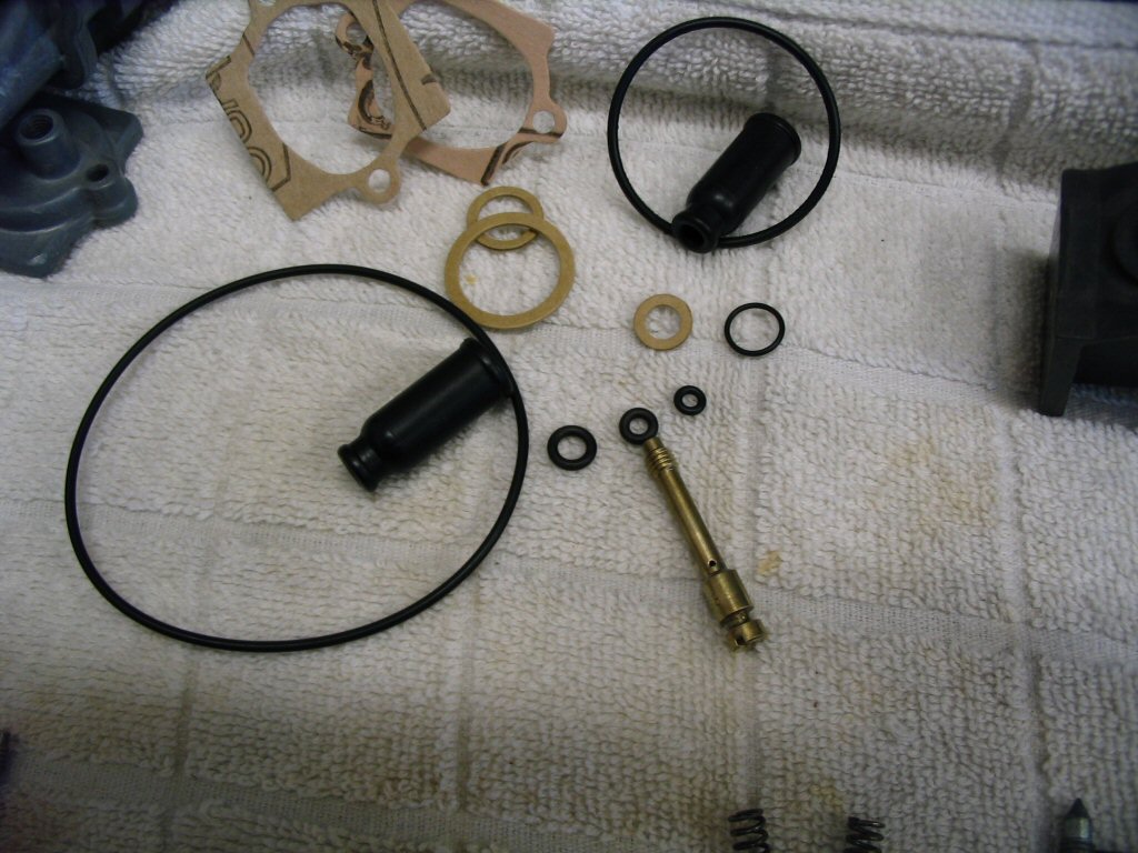
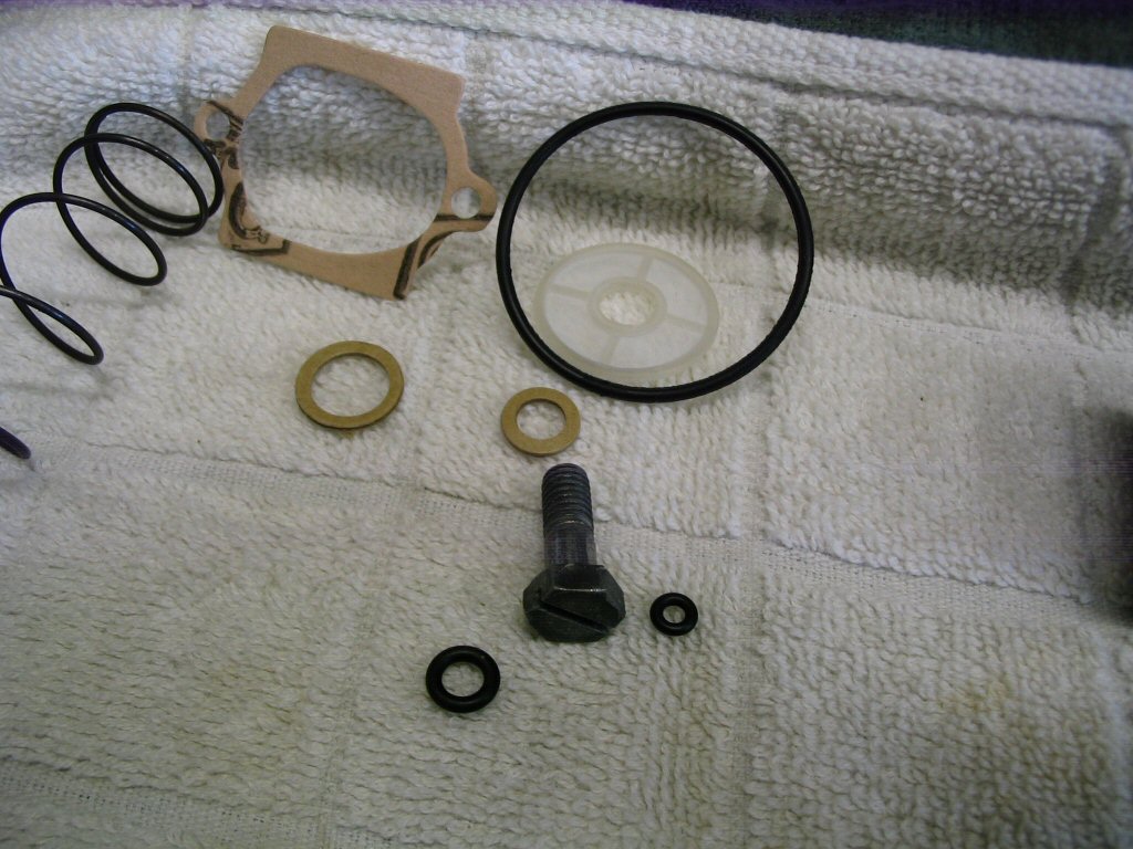
Note: Always take care when fitting O-rings such that they are not damaged during installation, particularly O-rings that slide into the body of the Dellorto VHBZ carburetors (as used on small block Moto Guzzis). The starter O-ring and top cap O-ring both require careful attention. It is a good idea to push the cap fully home before screwing down the screws.
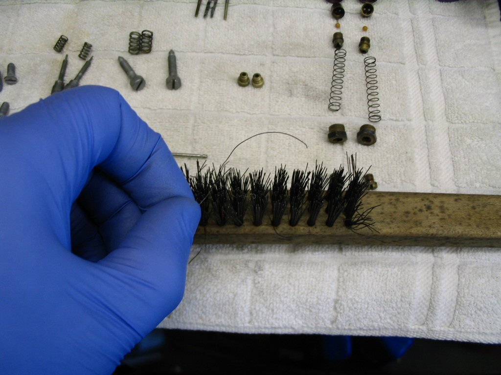
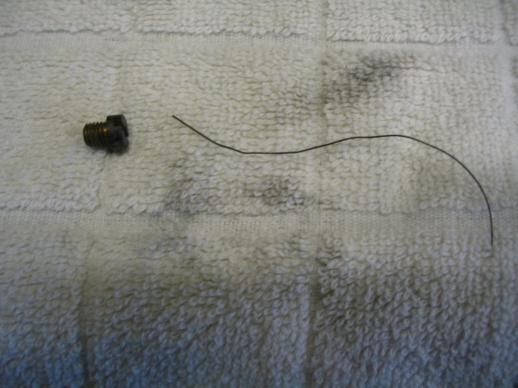
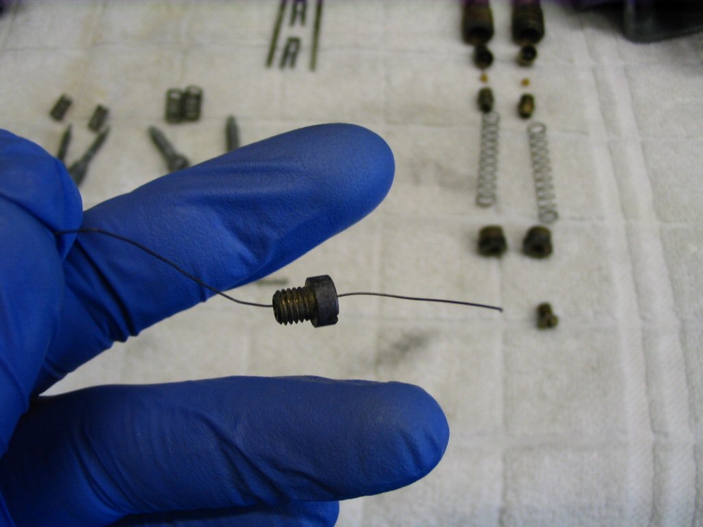
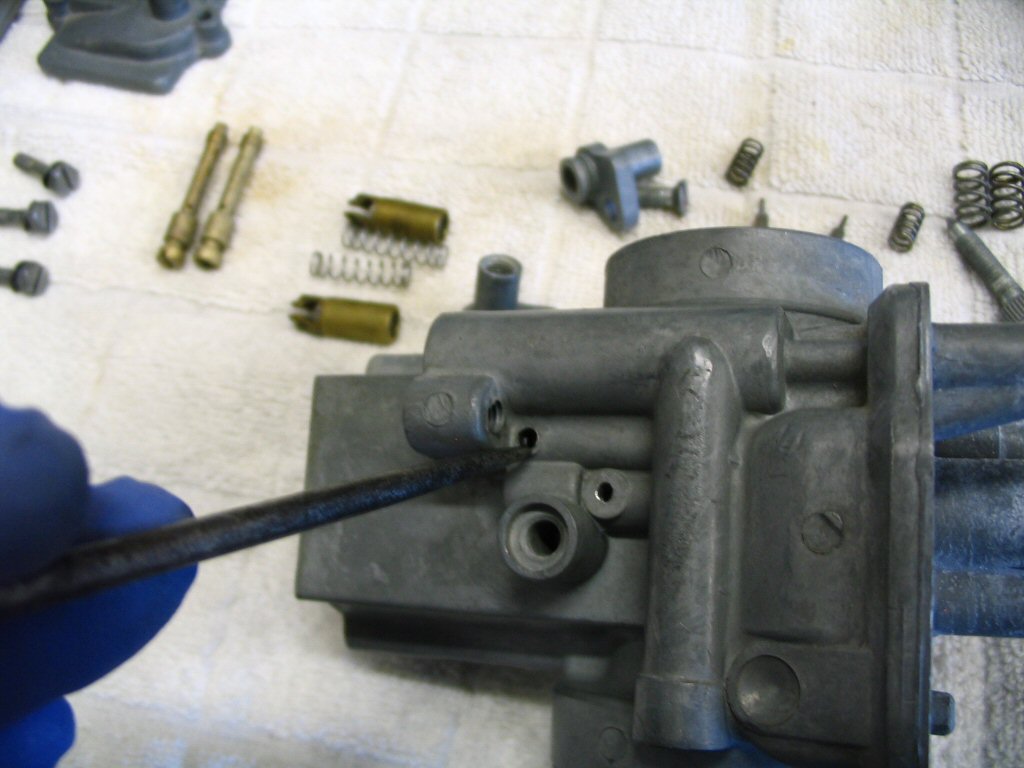
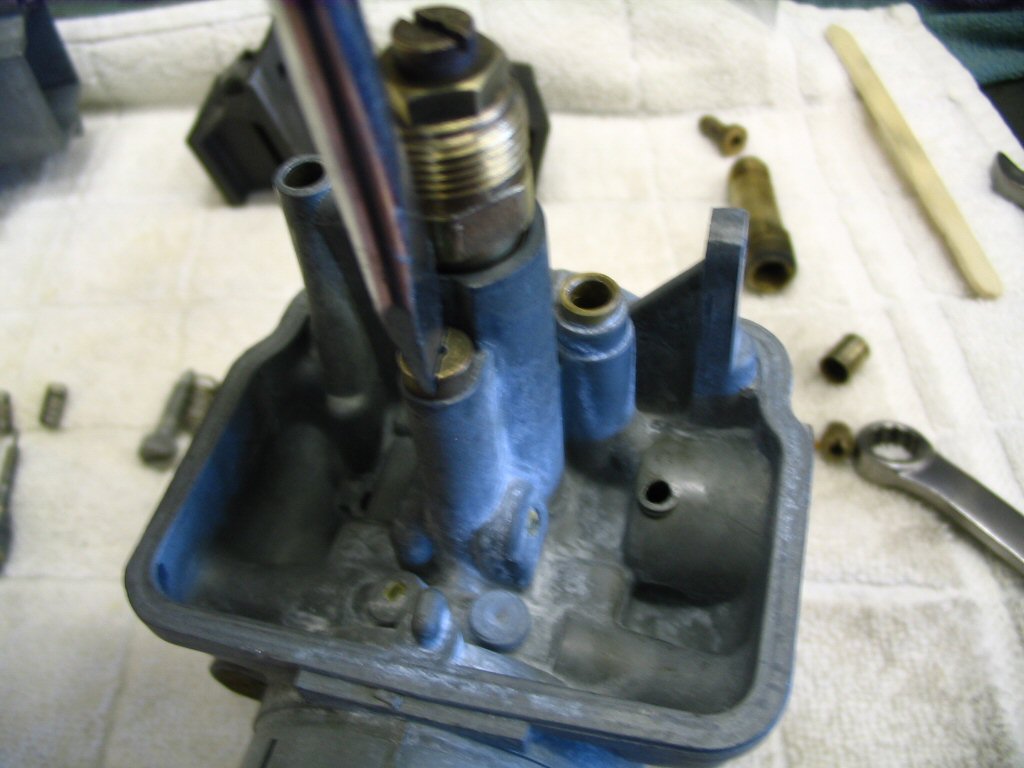
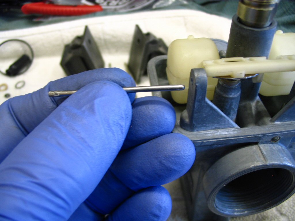
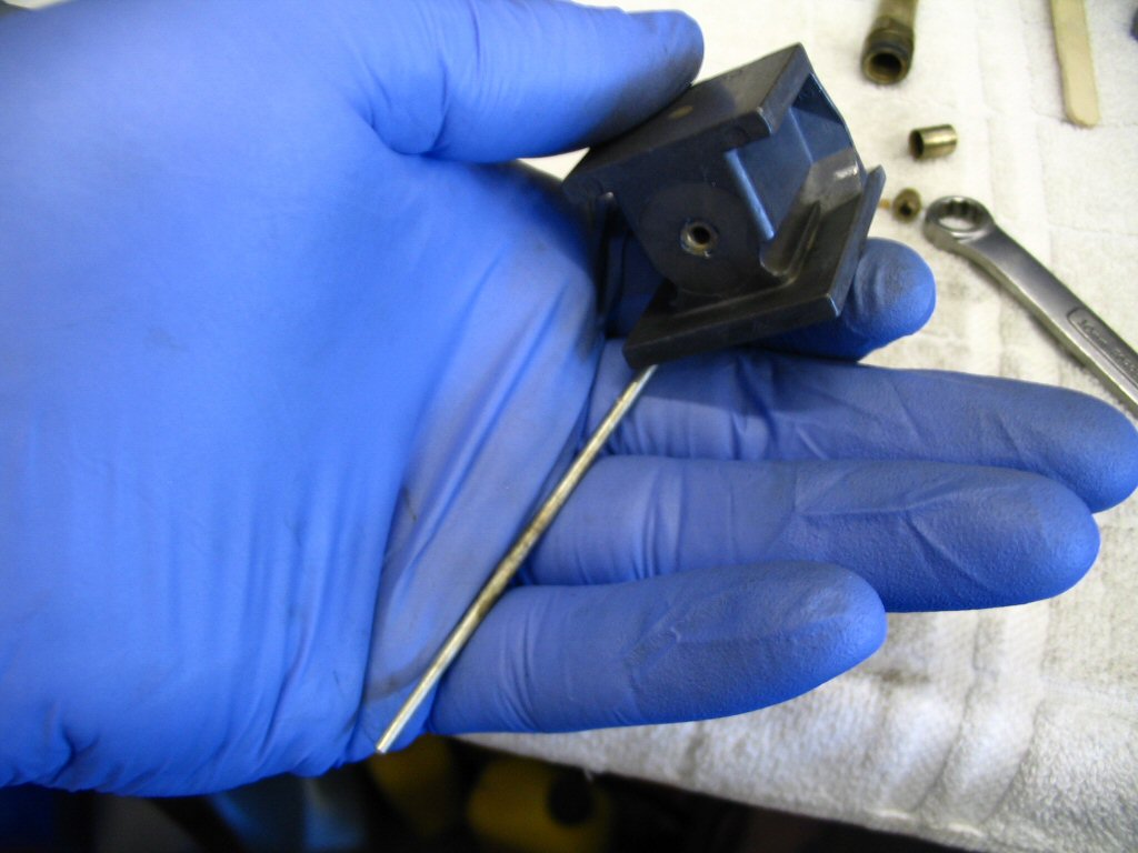
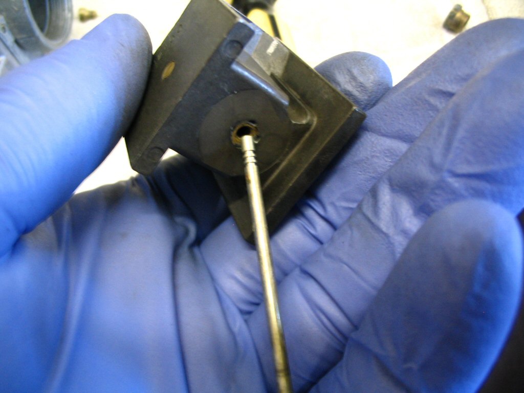
Insert the wire through the jet and spin the jet around a few times with your finger. Repeat with all the holes in all the jets: both main jets, both idle jets, both choke (enricher) jets, and both atomizers. Quick, simple, done. I learned this tip from my Dad, Tom Bender.
As an alternative to using a wire from a wire brush, Joe Tokarz sent me his method:
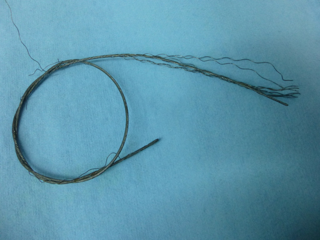
I have an alternative wire for carb jet cleaning. I use stands of wire plucked from old control cables.
Throttle wires are the thinnest, and front brake is thicker.
The wire is stiff and has a natural ripple to it and that makes orifice cleaning easy. Just be sure to cut the end clean; no burs. The wire can be straightened with pliers if needed.
With this in mind I have been able to amass a supply of carb cleaning wires that will last for about 200 years.
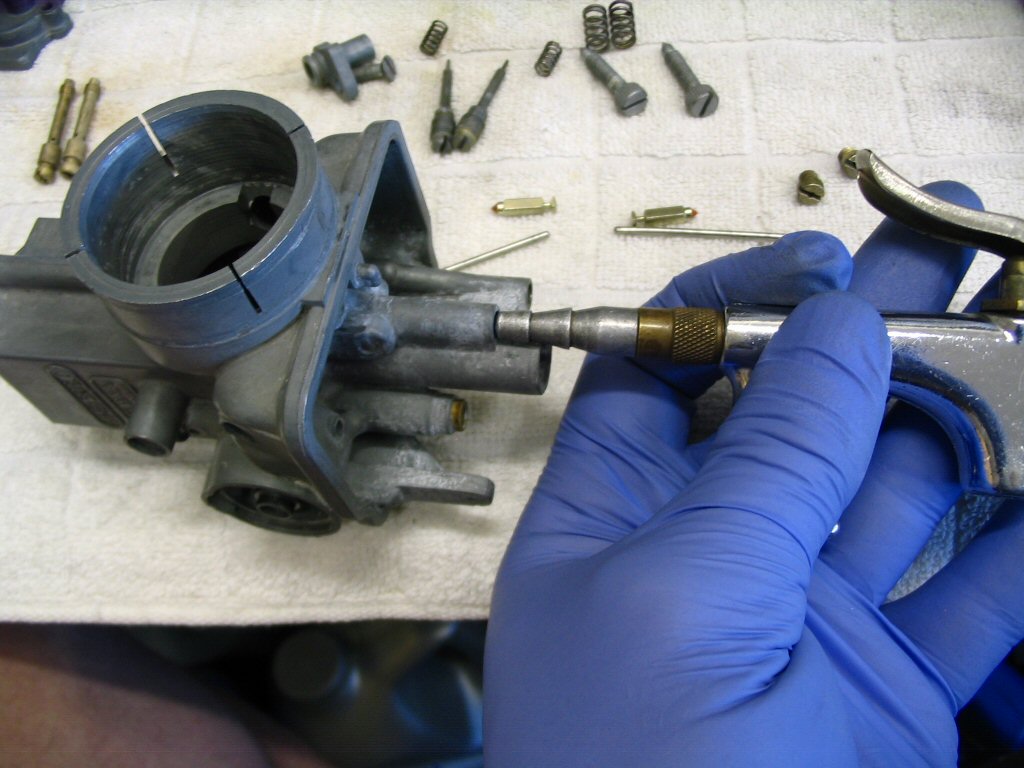
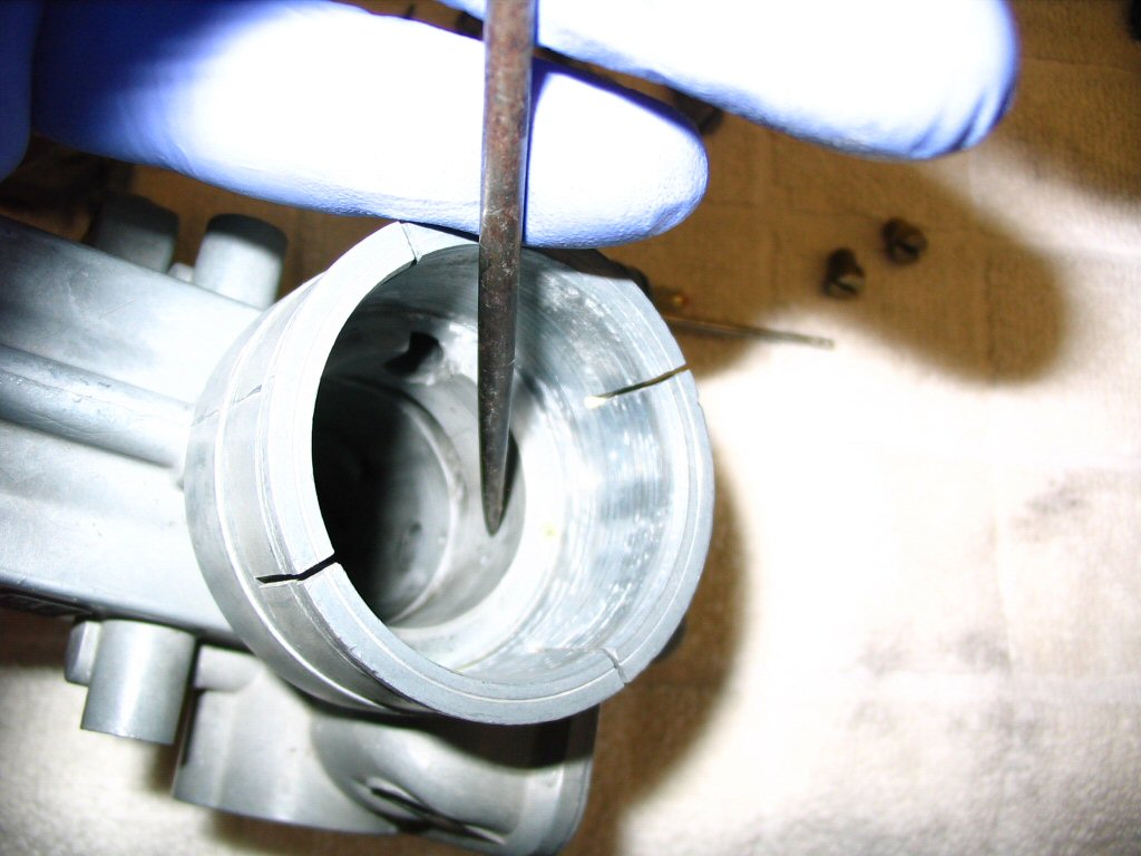
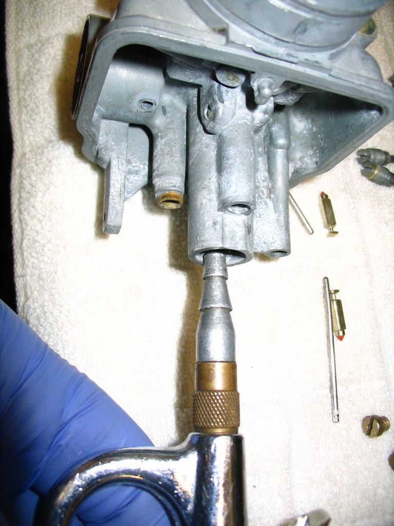
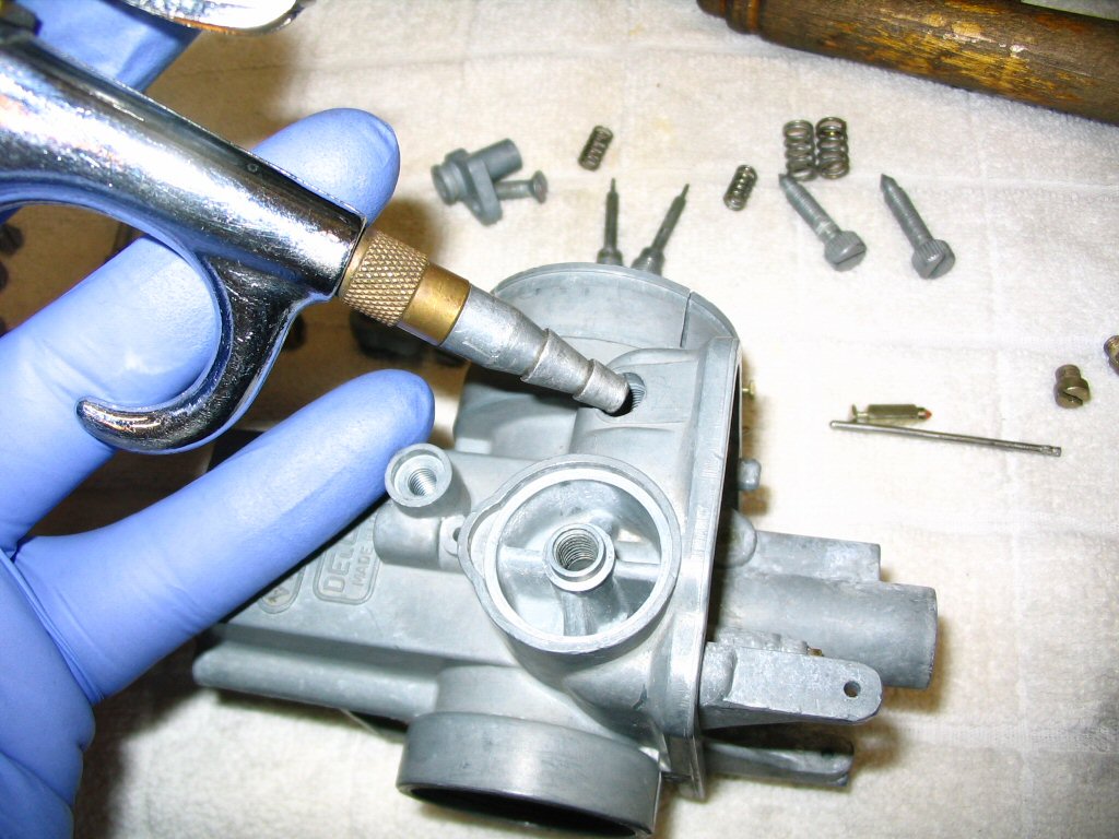
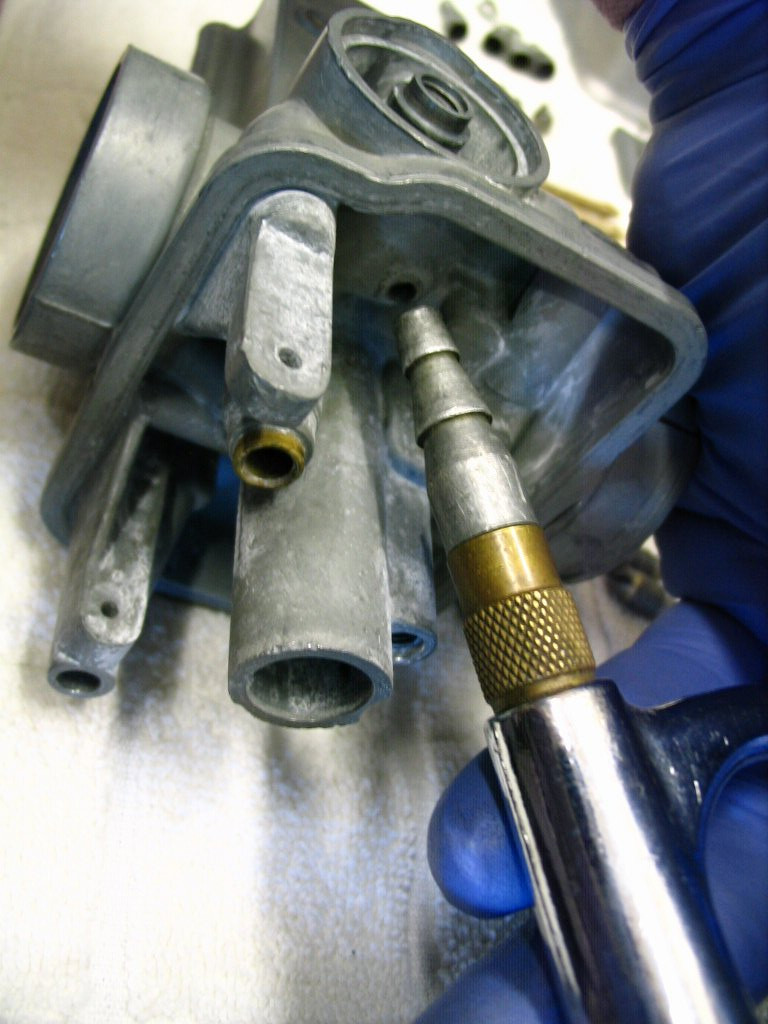
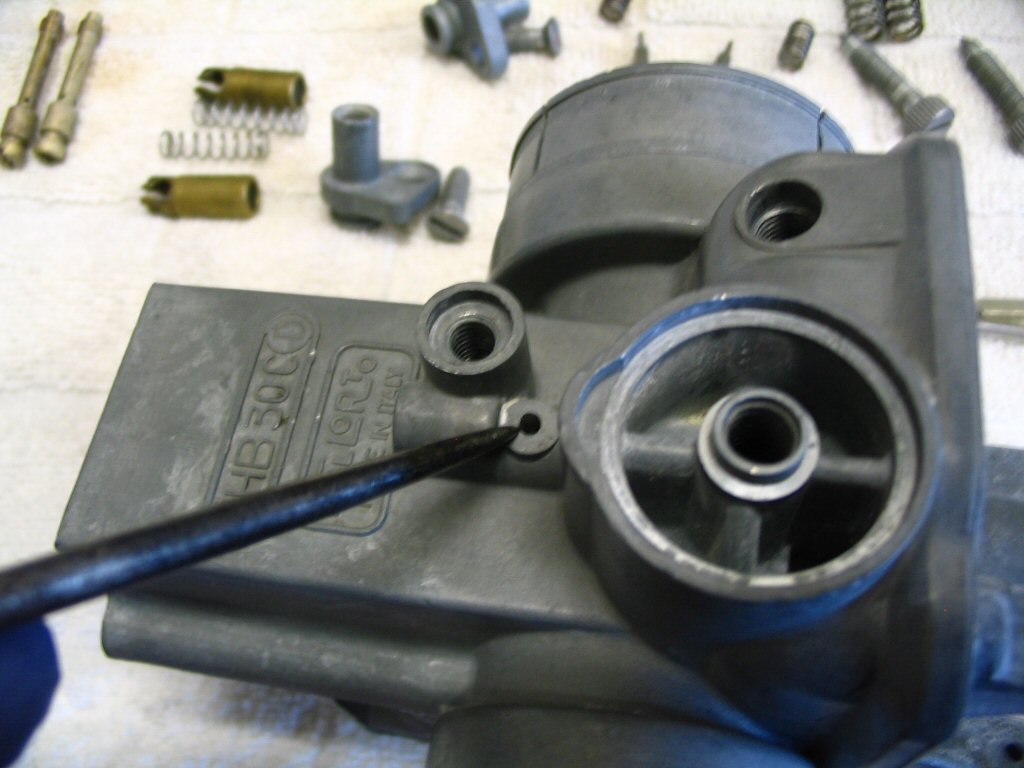
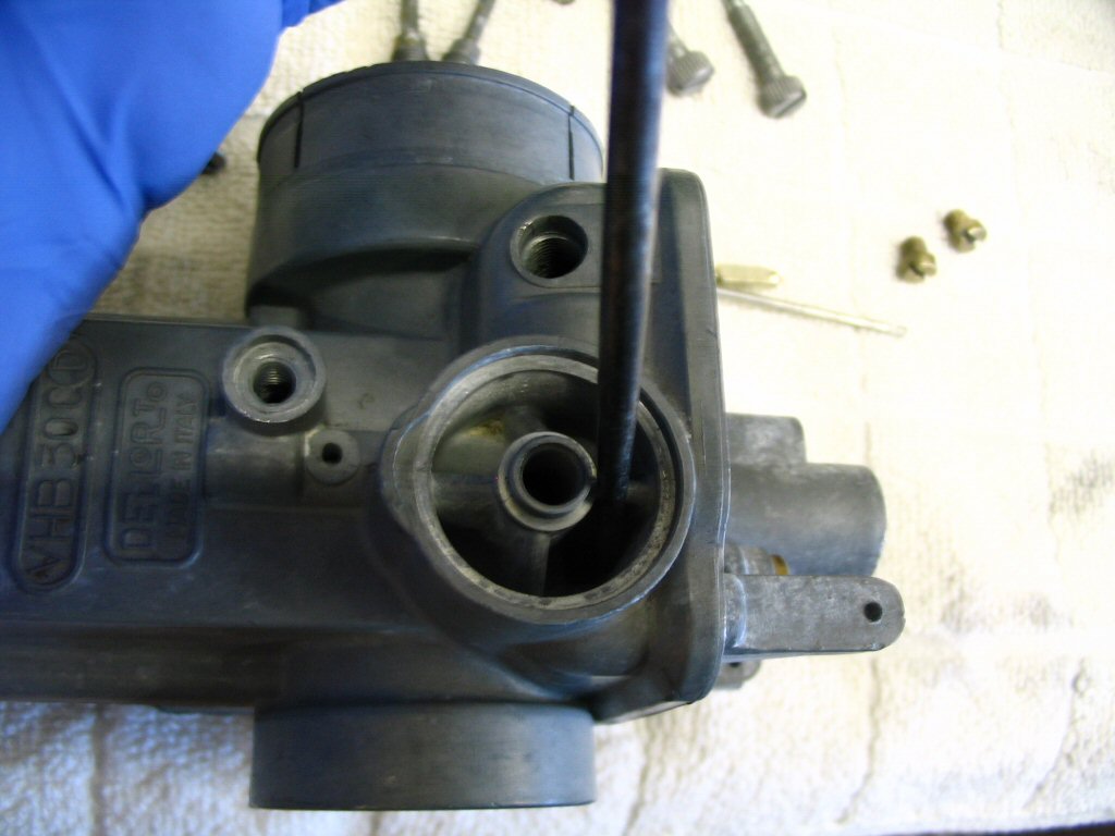
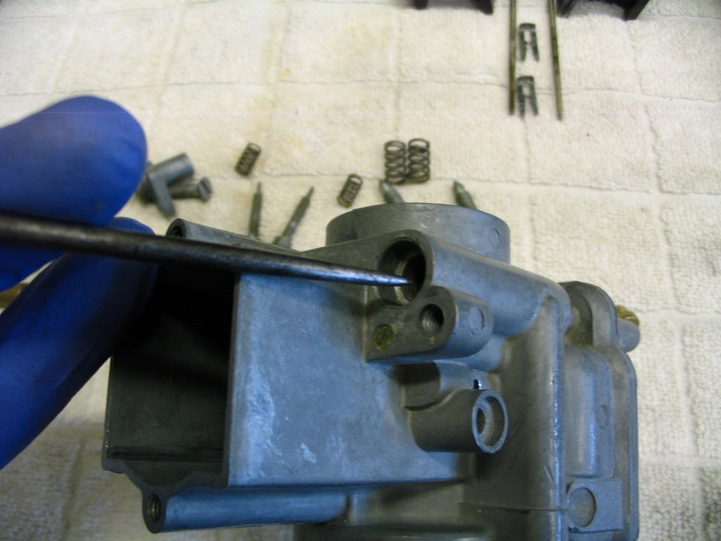
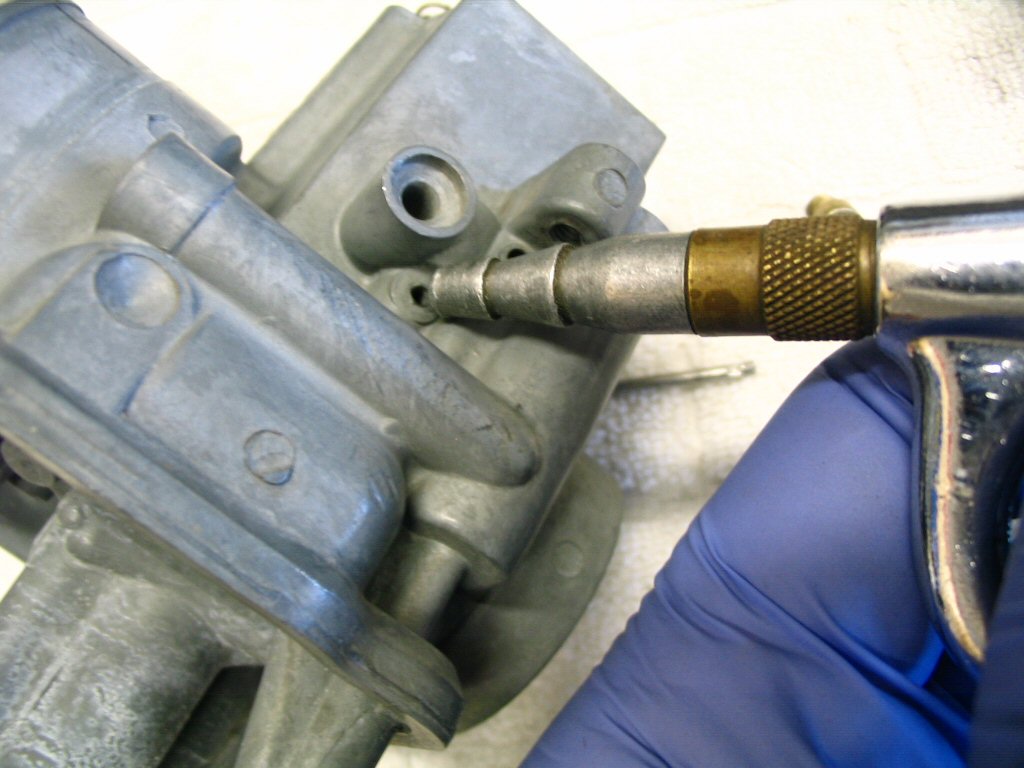
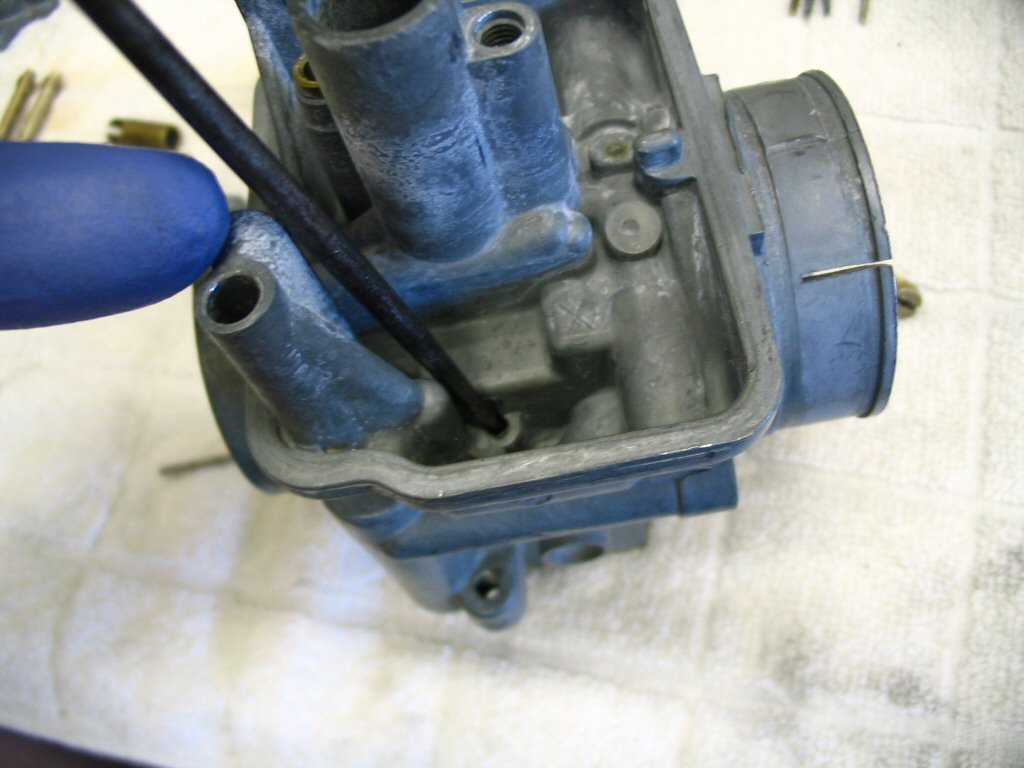
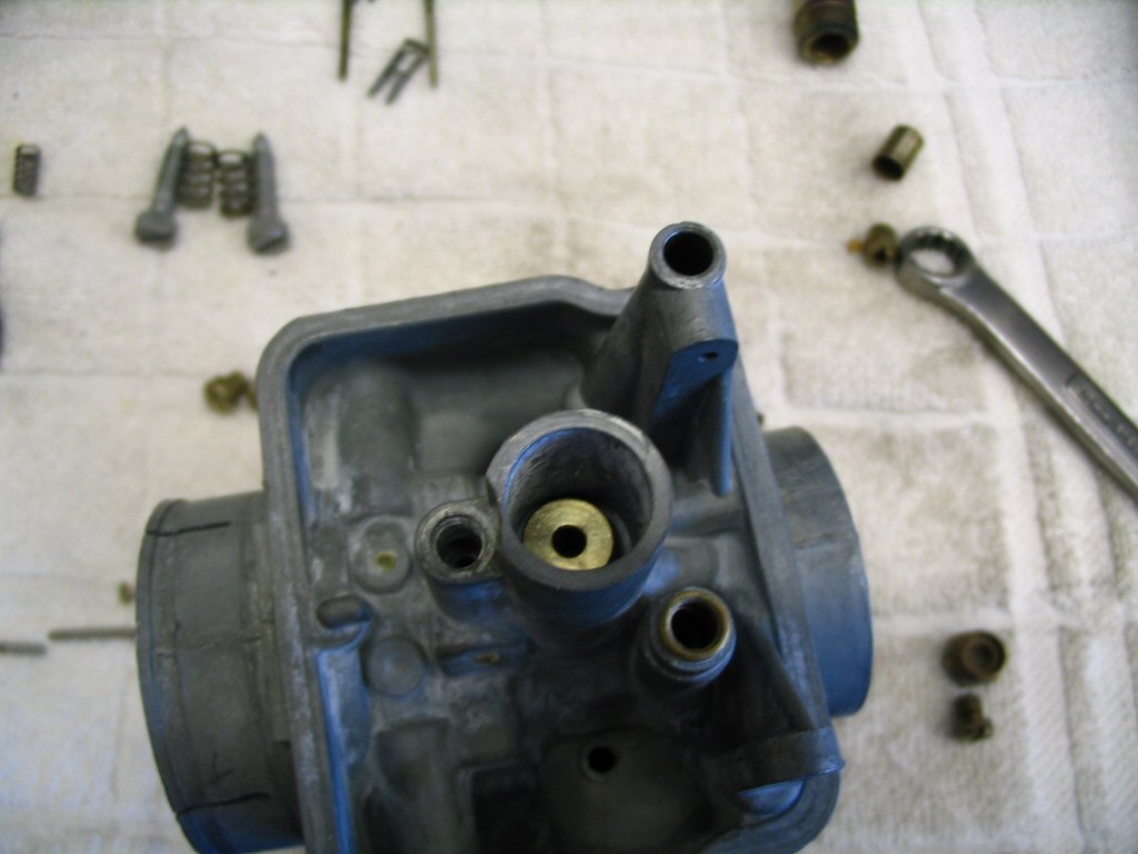
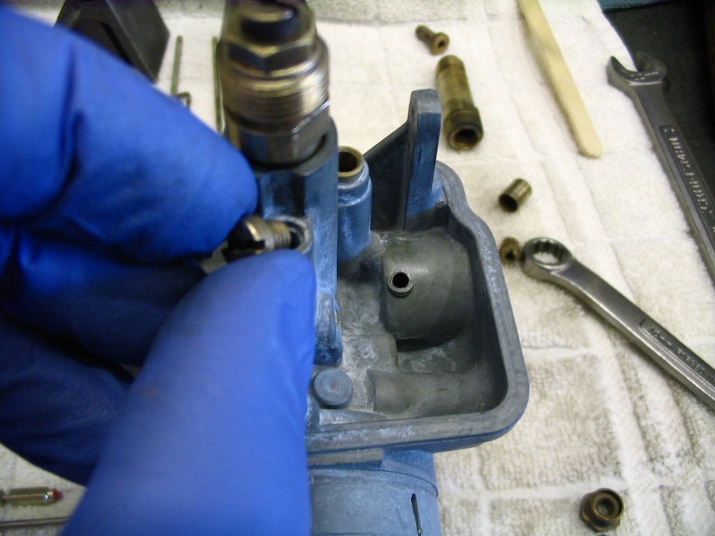
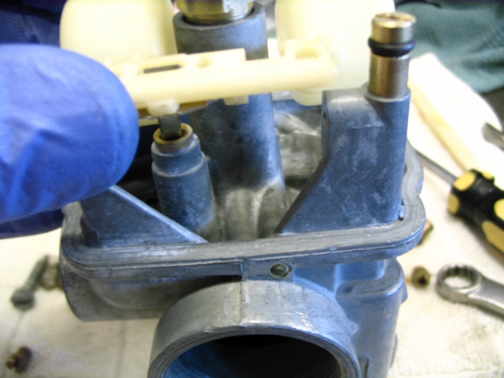
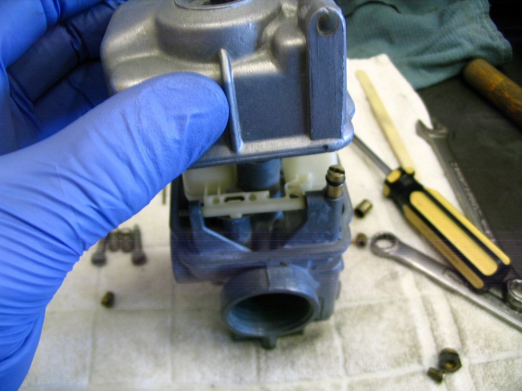
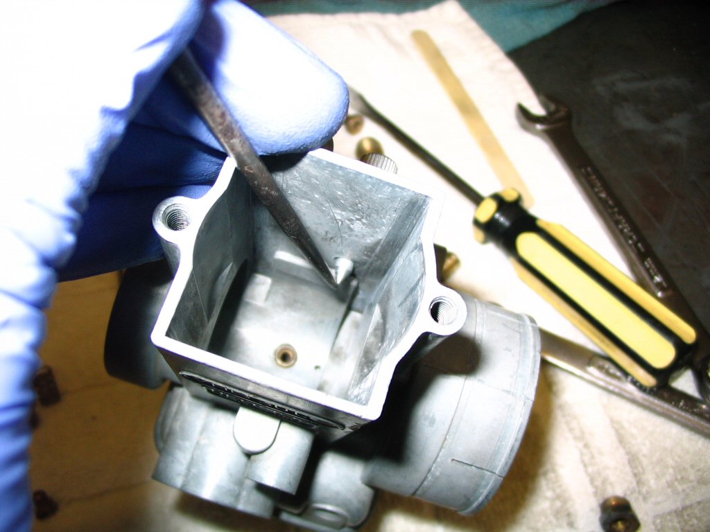
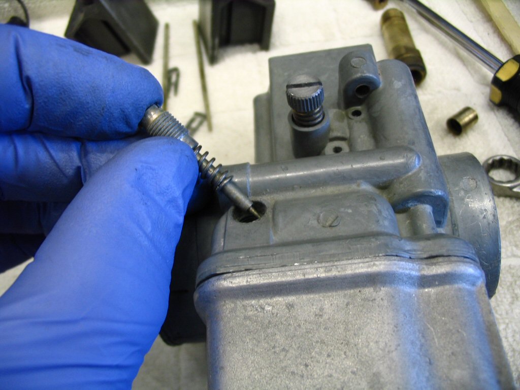
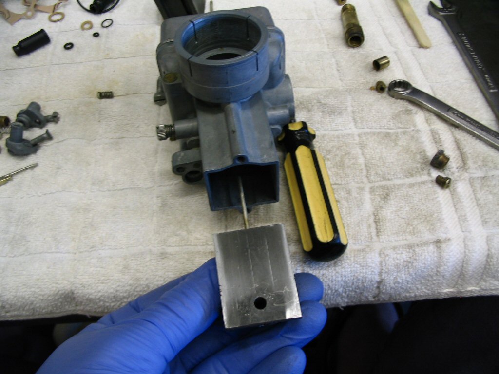
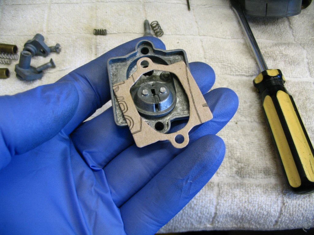
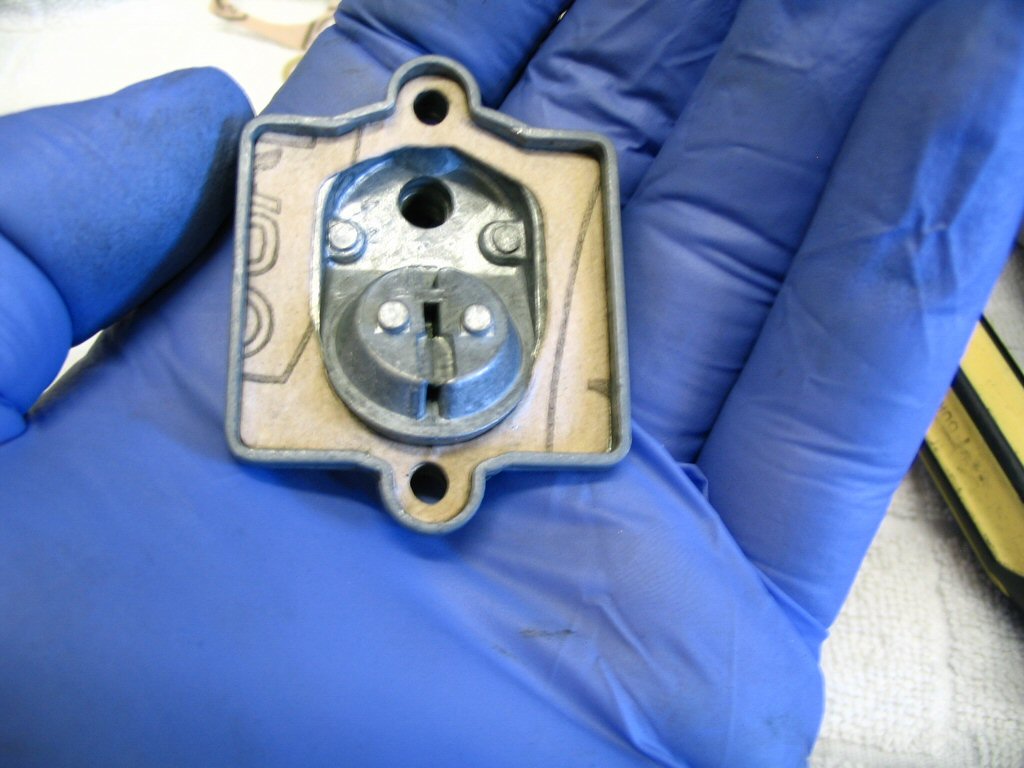
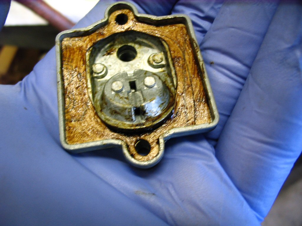
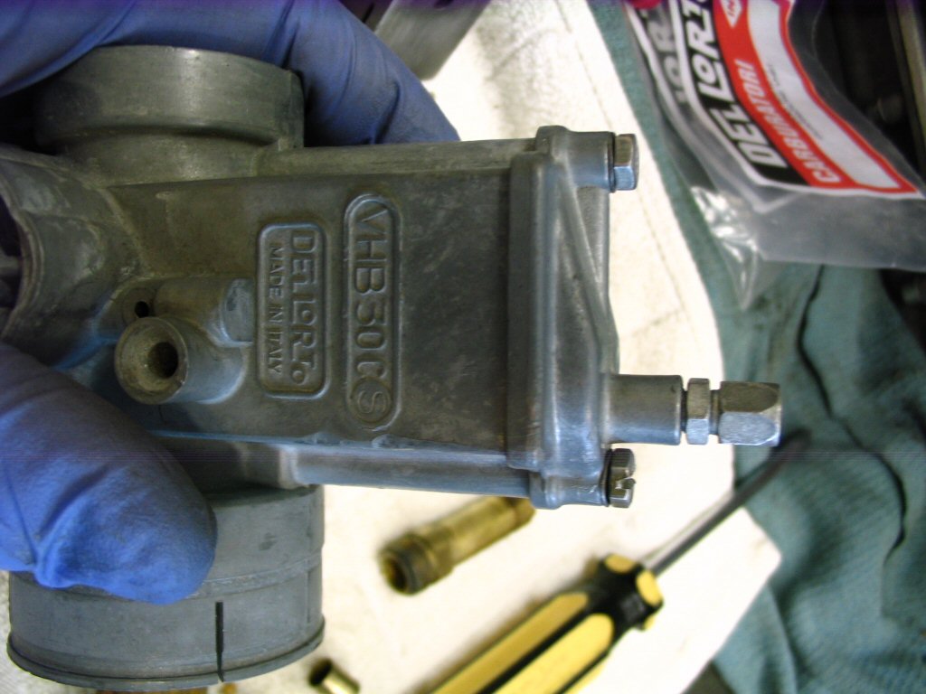
...you should feel air escaping from (a) the mixture screw hole, (b) two tiny holes in the throat of the carb (you've shown one - there's another closer to the atomizer hole IIRC) and (c) a small port at the inlet near the threads for the velocity stack (thanks to Charlie Mullendore of Antietam Classic Cycle for assisting in identifying air escape locations).
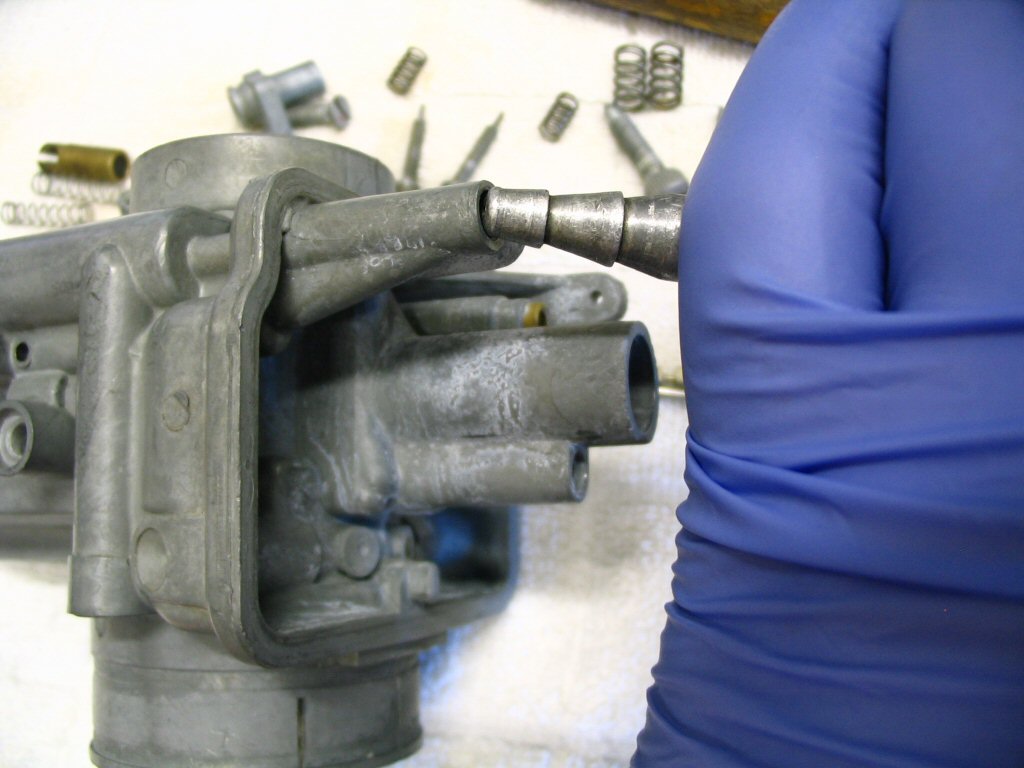
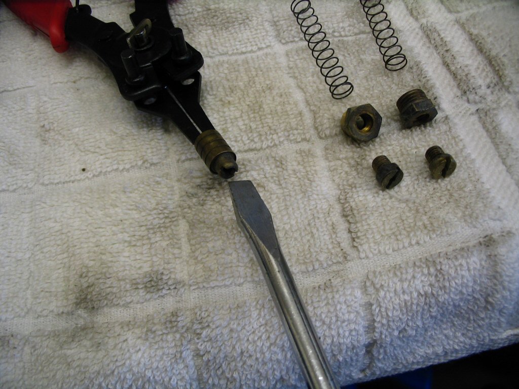
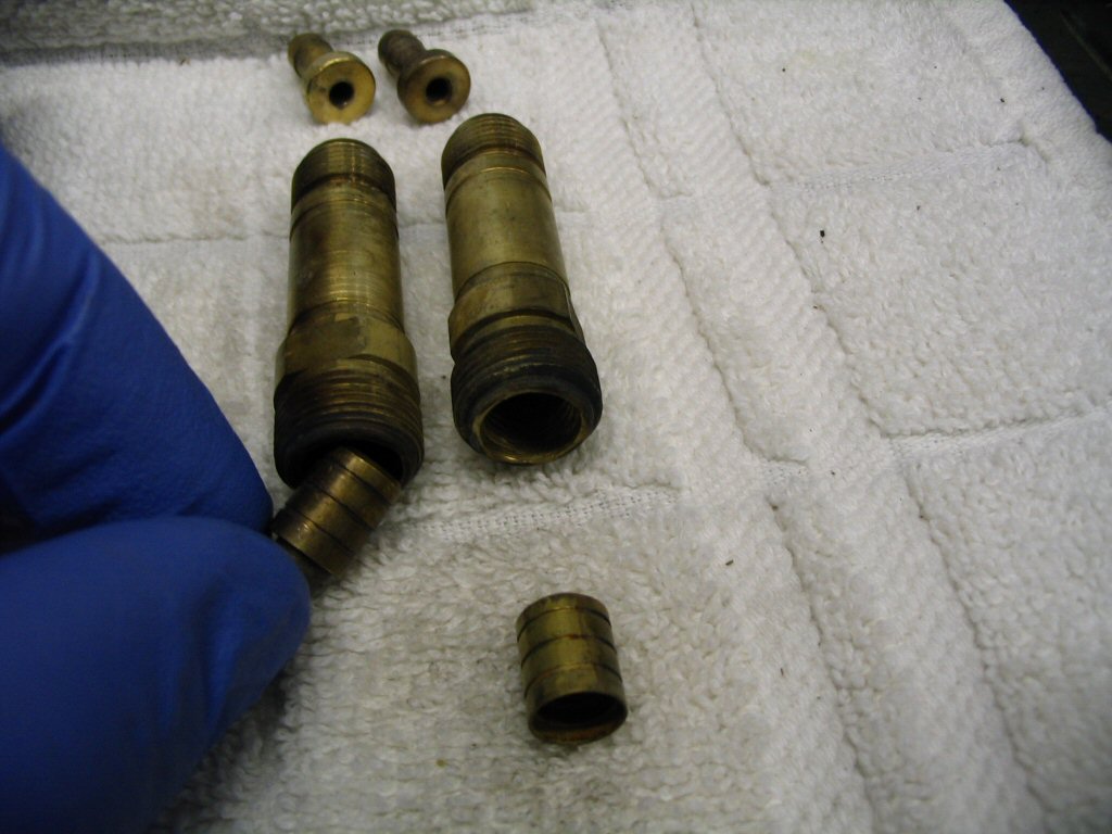
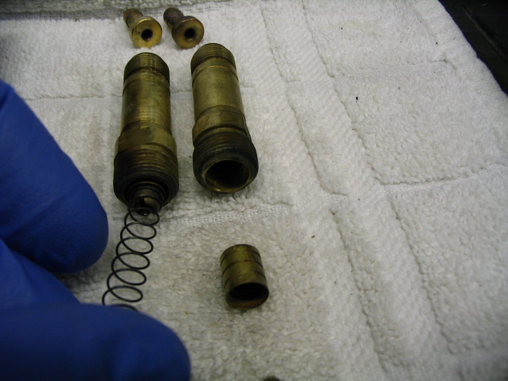
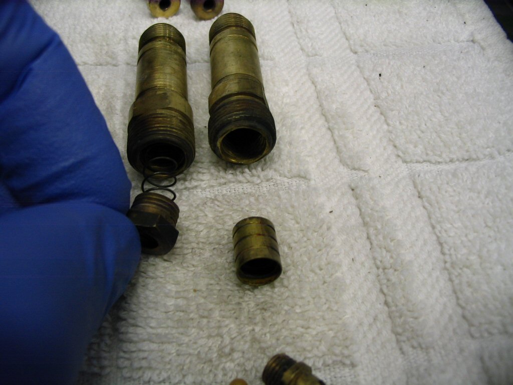
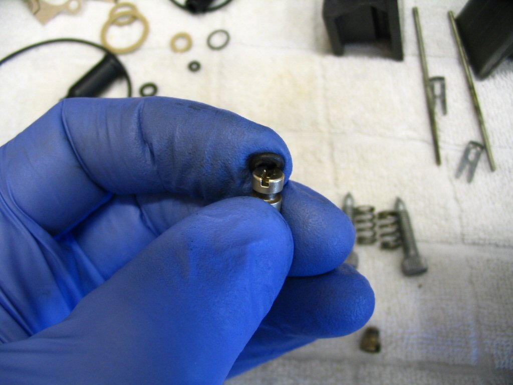
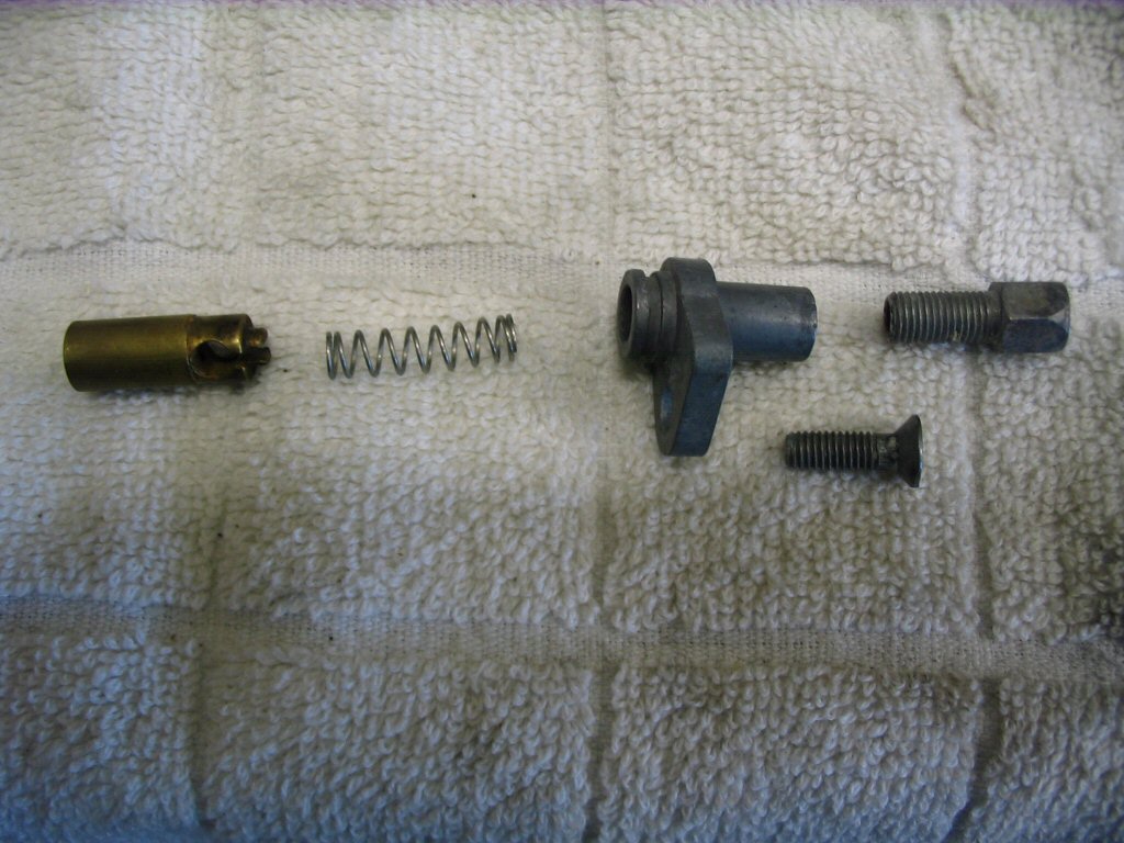
Note: Some prefer not to disassemble the accelerator pump piston; choosing instead to consider it perfectly functional if they hear the plastic ball bearing rattle inside the accelerator pump piston.
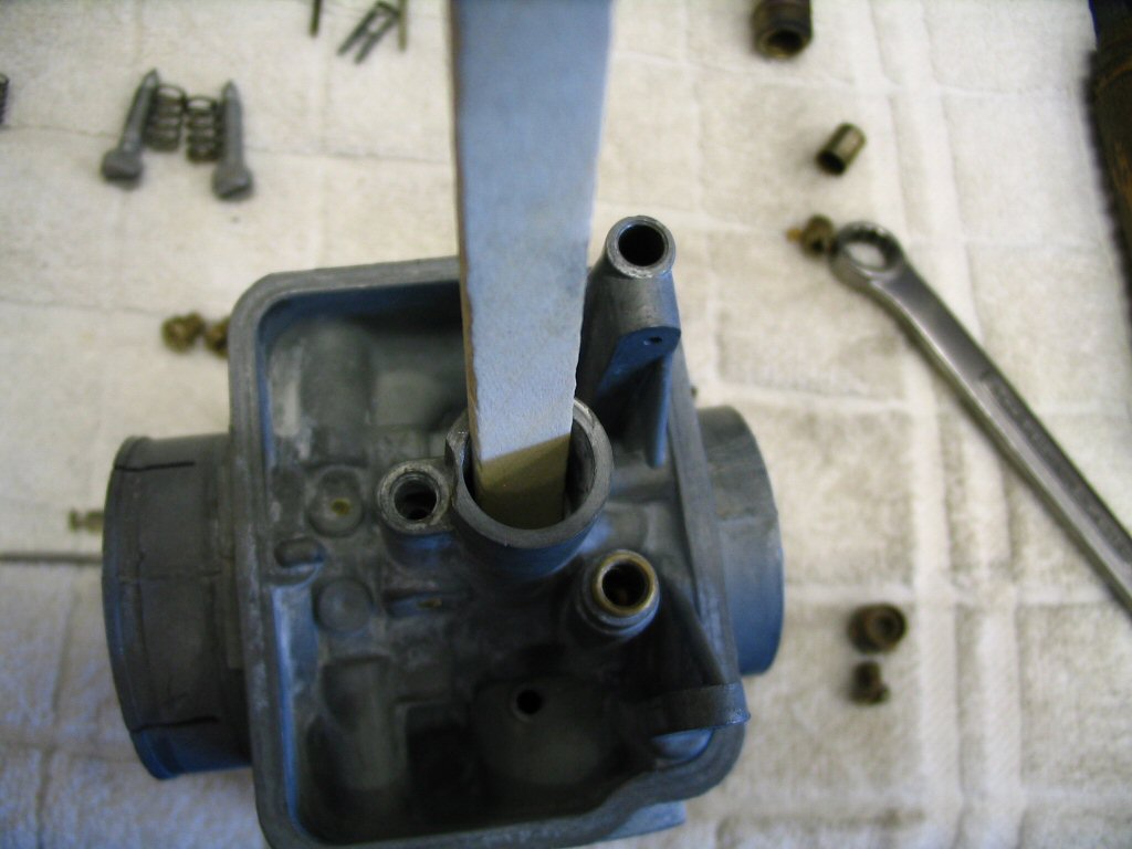
Use a wooden popsicle stick to push the atomizer into place. The wood is soft and you will avoid damaging the atomizer. I learned this tip from Charlie Mullendore of Antietam Classic Cycle.
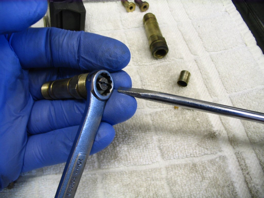
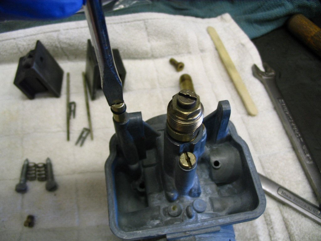
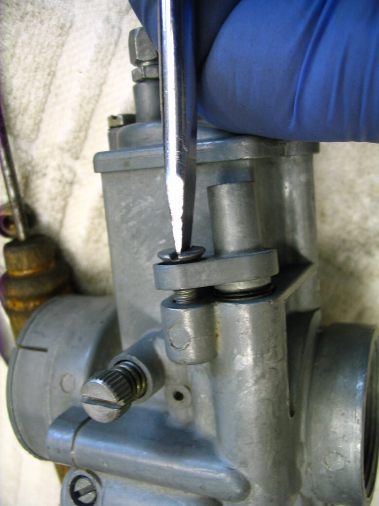
And tighten with a screwdriver. Just a light snug. You should be getting a very clear picture by now that nothing on the carburetor requires much torque.
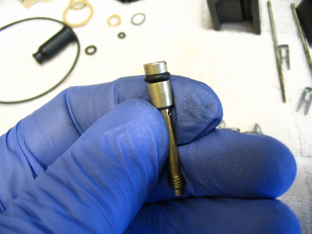
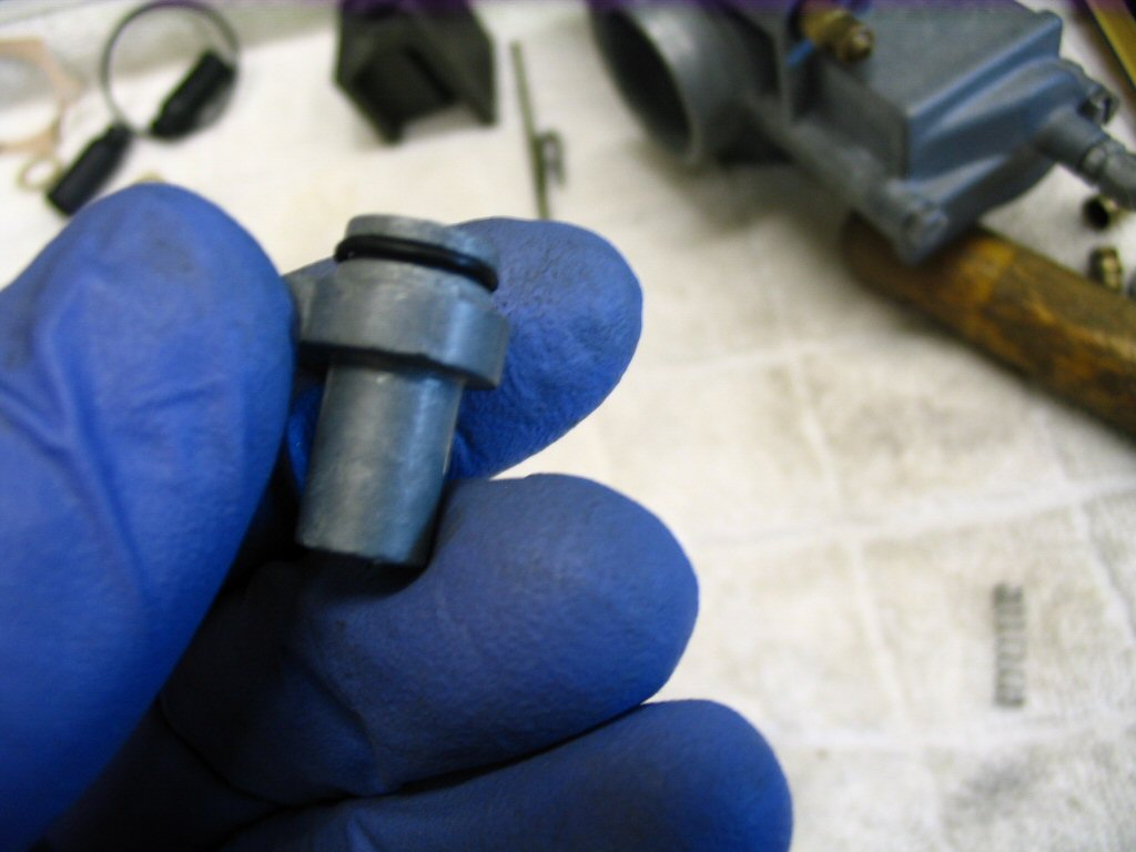
I position the O-ring like this, and then push it over the top. I've found this method easier than trying to bring it up from the other end. Charlie Mullendore of Antietam Classic Cycle prefers to slip it up over the threaded end first, then work it over the larger end into the groove. Either way works fine. Charlie recommends using silicone spray lubricant on the O-ring to help it slip on easier.
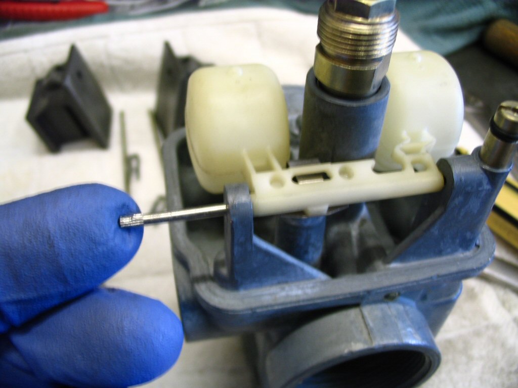
And push it through to the other side. USE YOUR FINGERS ONLY! There is no need whatsoever for the float pivot pin to be hammered or wedged into place. If the splined end gets stuck too far in, the pin is very difficult to remove. The float bowl will prevent the pin from falling out, anyway.
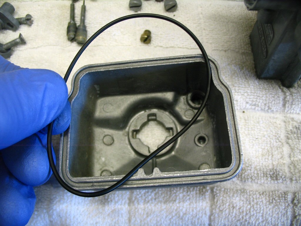
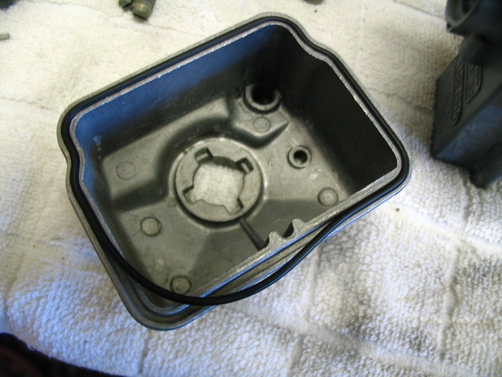
Now it is time to fit the large O-ring to the float bowl. It is easier to do if the O-ring and float bowl are warm. So, if you are working in the winter months, just take it inside the house and let it warm up.
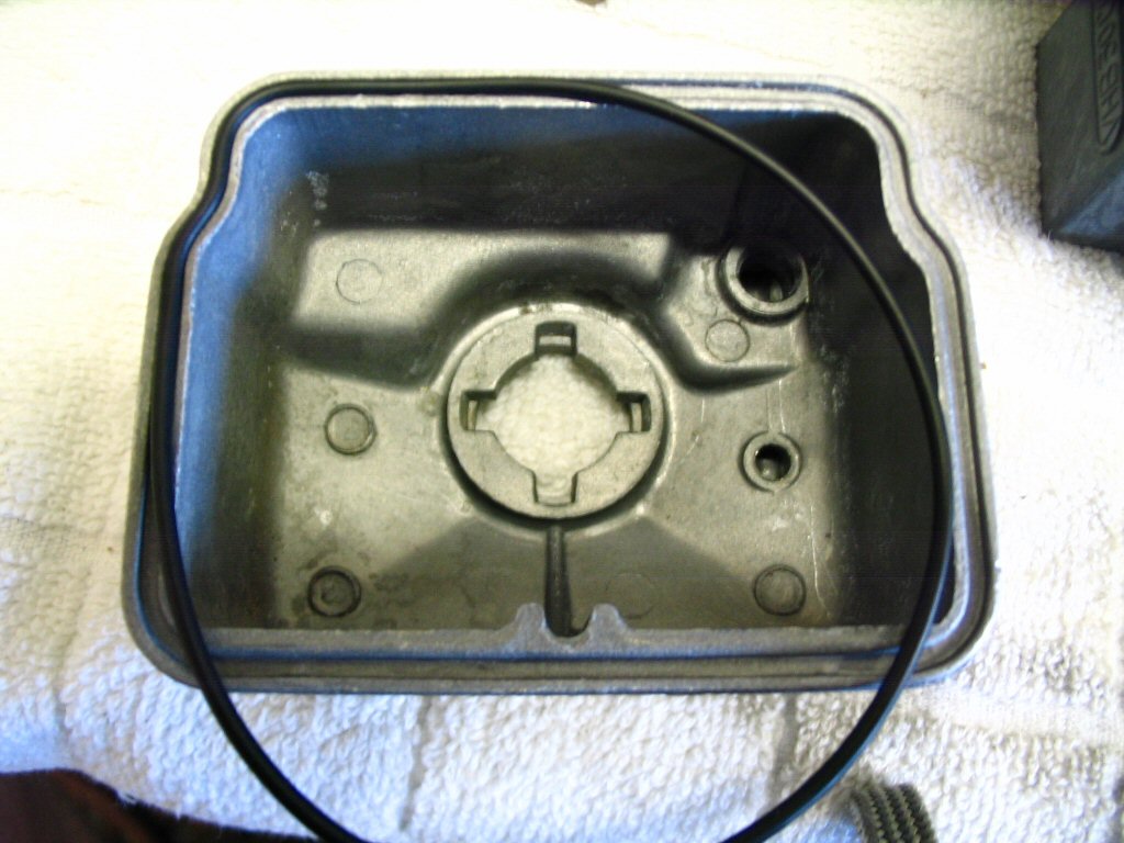
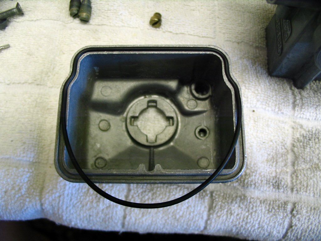
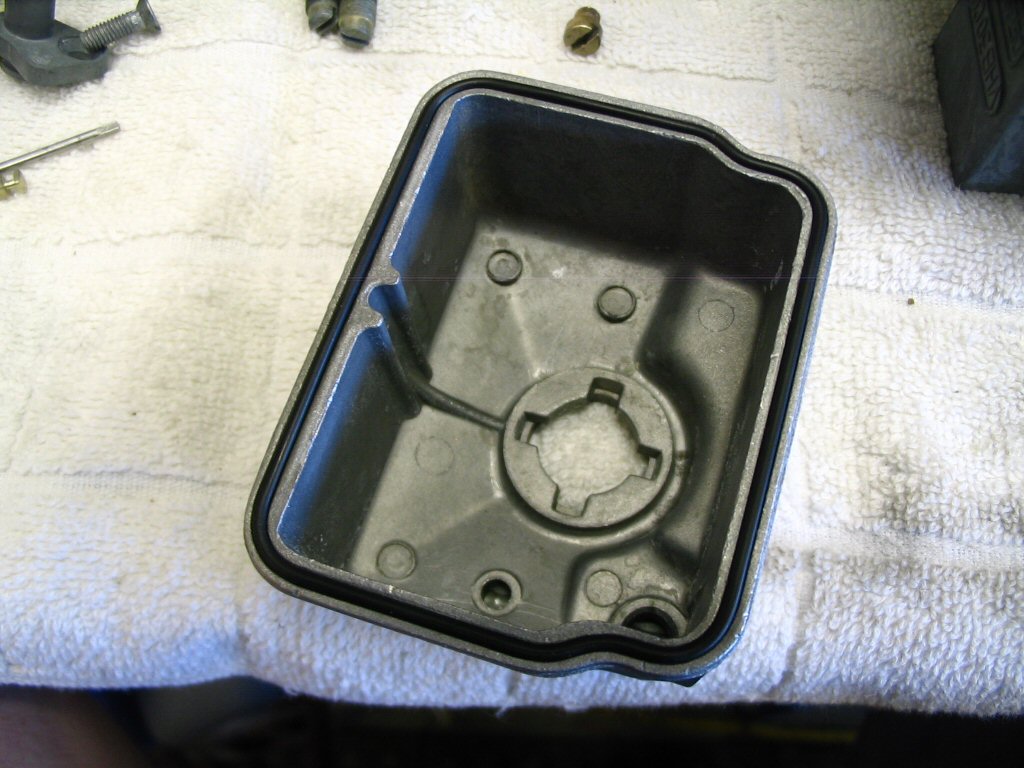
Up to now, fitting the O-ring has been easy. Now comes the tricky corner. If you roll the O-ring into place, it will immediately try to roll back out. You can fight it for eternity (or until the O-ring breaks) and it'll still want to roll out. The trick is to roll it in the opposite direction just a bit using your thumb and forefinger, and then roll it into place. This neutralizes any roll and the O-ring will stay nicely in place.
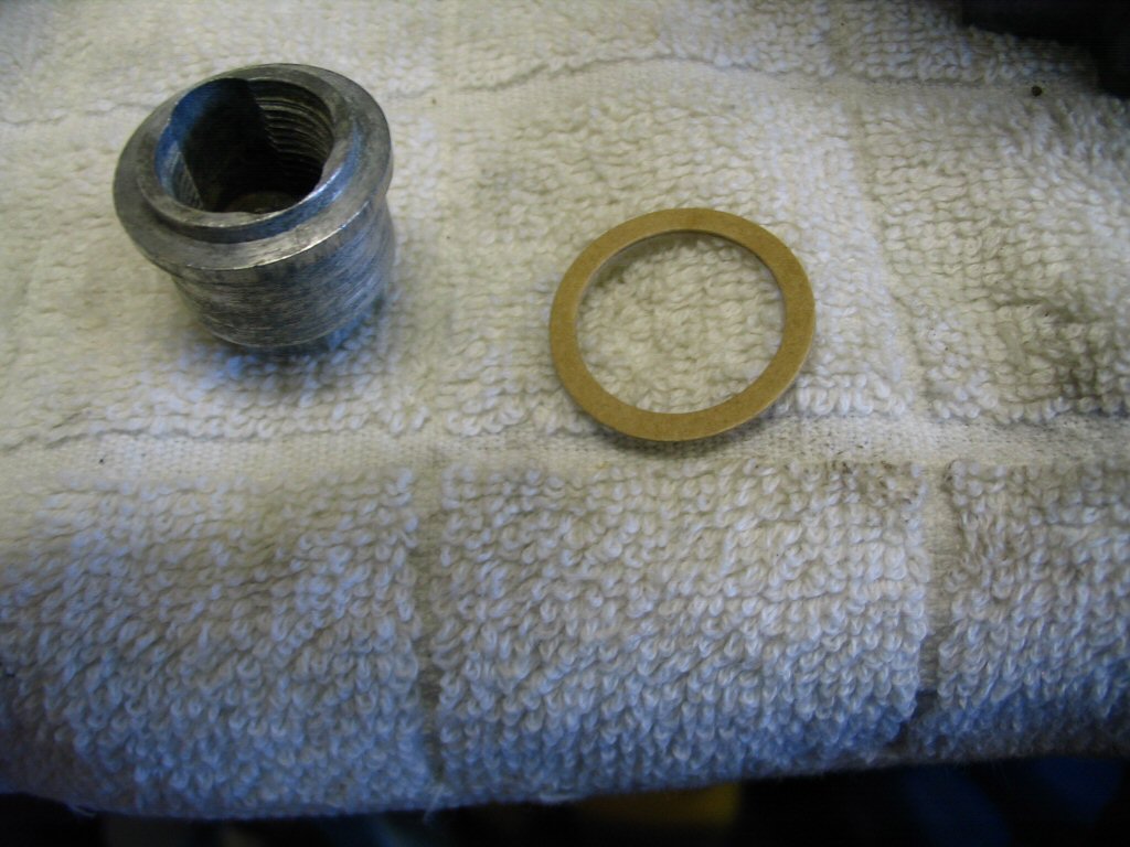
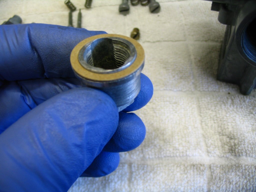
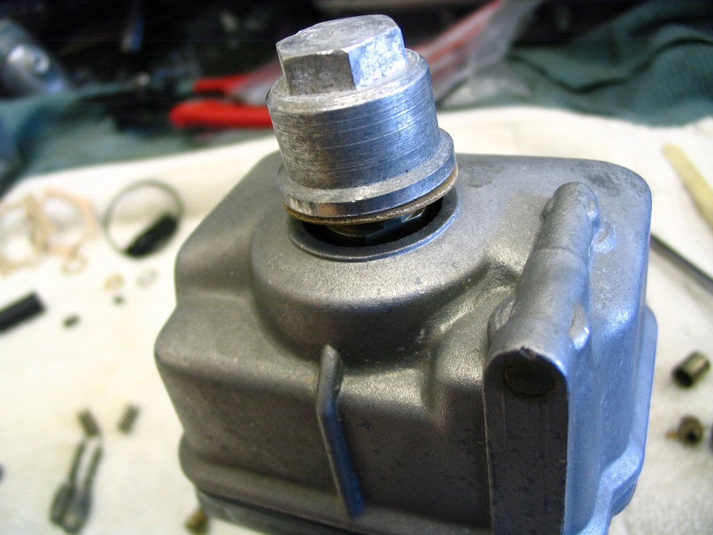
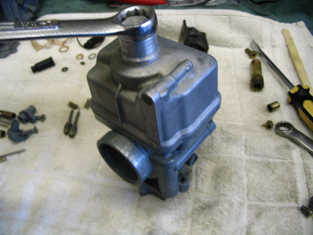
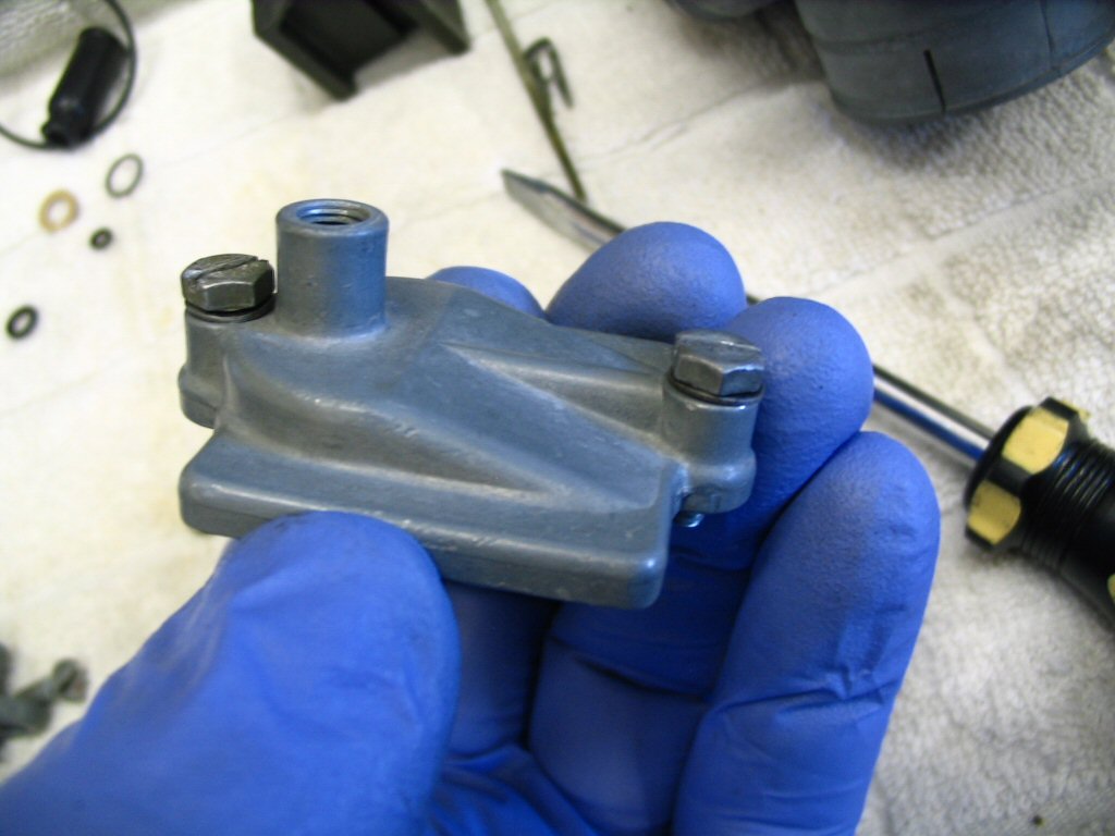
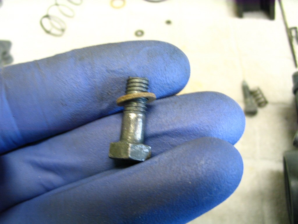
Fit the gasket to the float bowl nut. Charlie Mullendore of Antietam Classic Cycle uses a little dielectric grease on the gasket to help it tighten down easier.
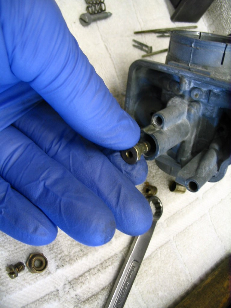
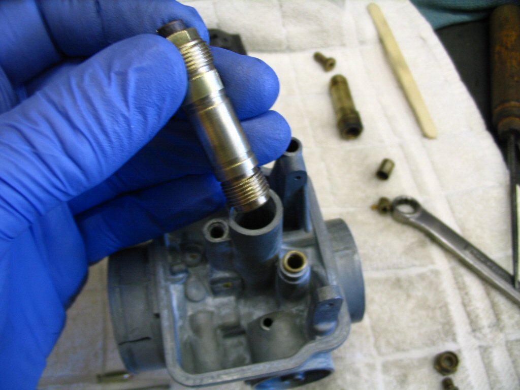
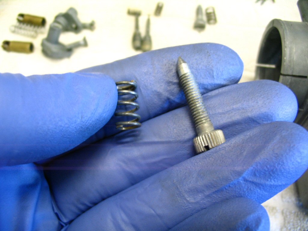
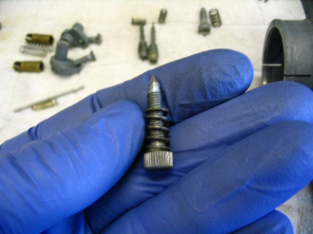
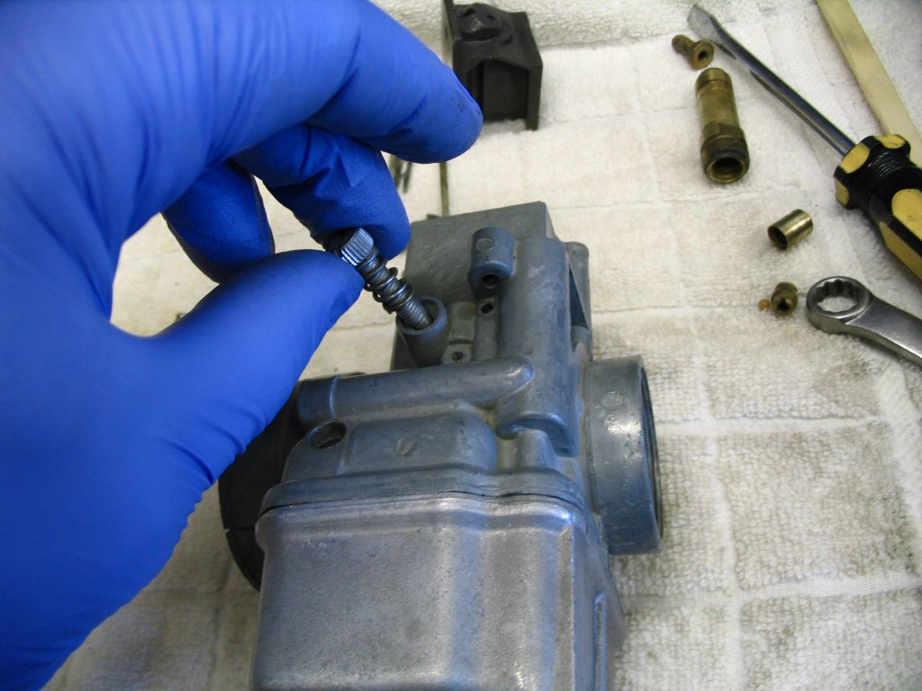
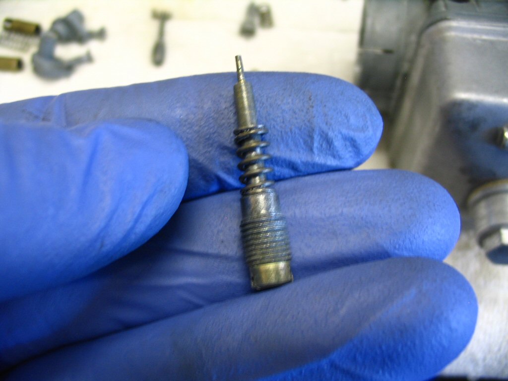
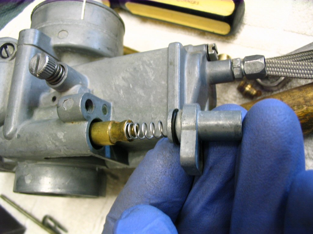
Insert the mixture speed screw and spring into the body of the carburetor. Screw it in until it bottoms out. DO NOT OVERTIGHTEN! Just bottom it out gently. Then, back it out the number of turns specified by the workshop manual (generally 1 1⁄2 - 2 turns for the left carburetor and 1 3⁄4 - 2 1⁄4 turns for the right carb).
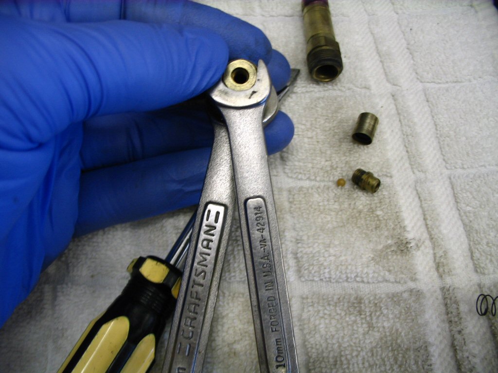
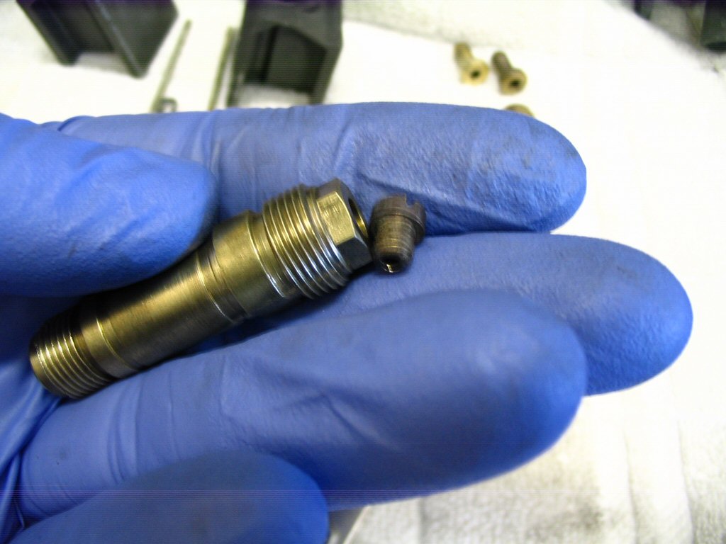
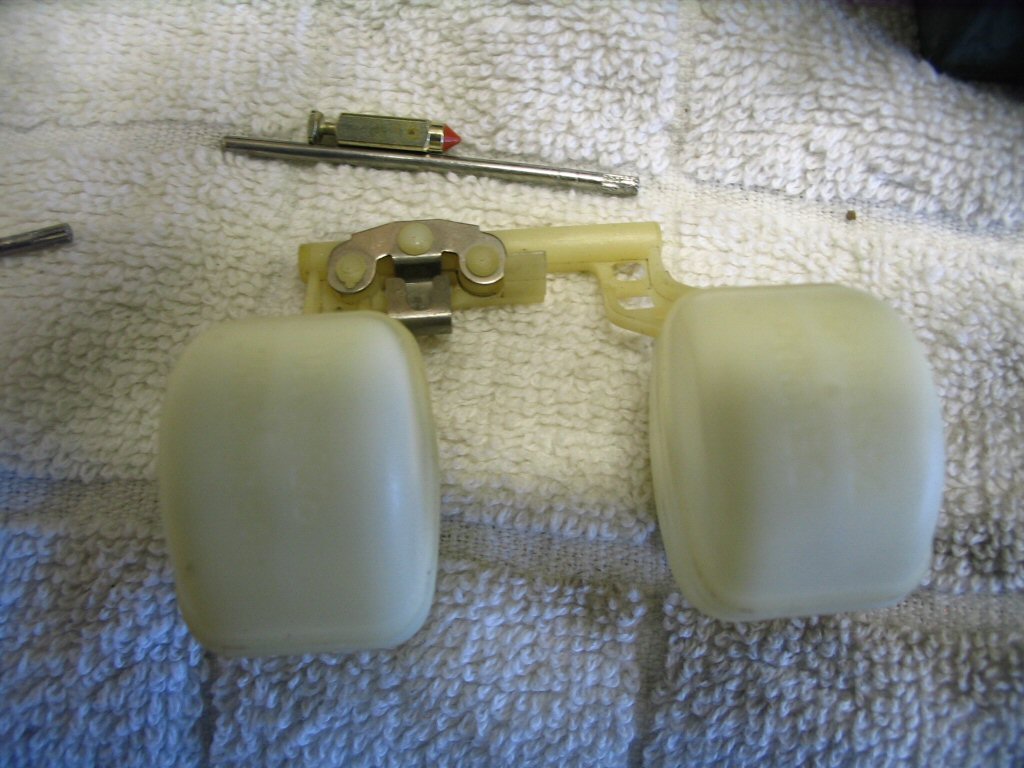
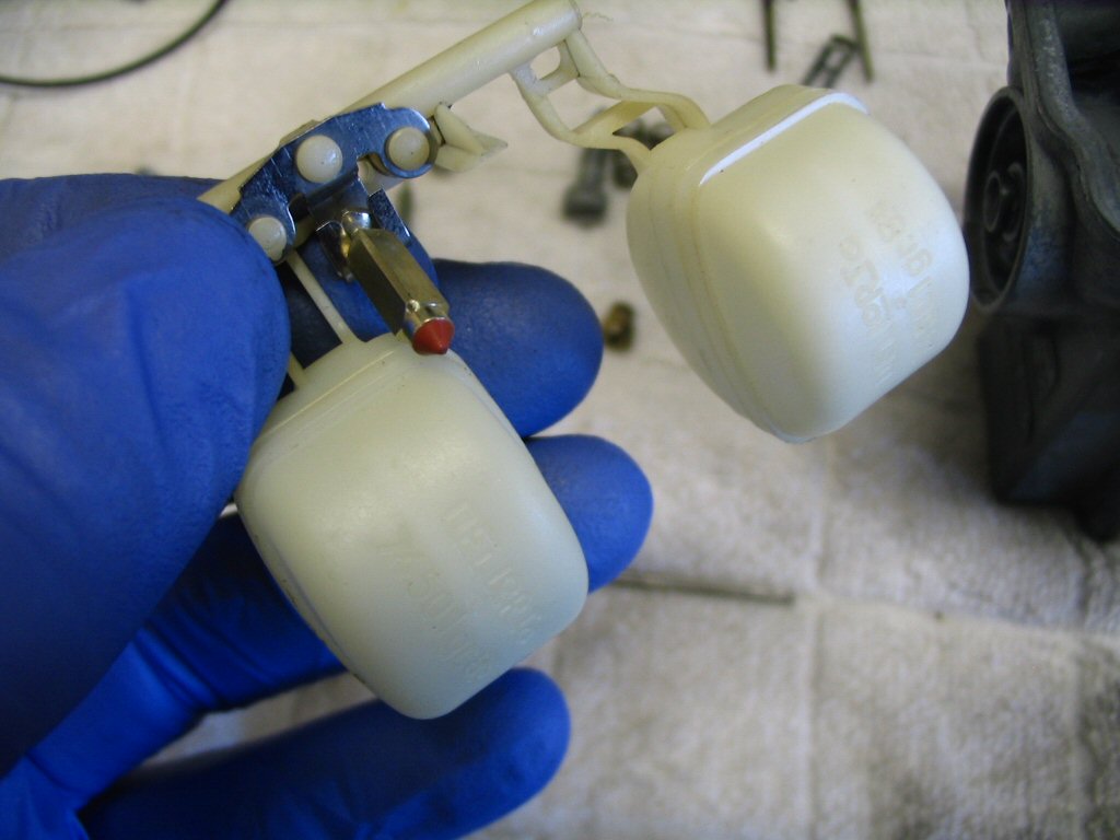
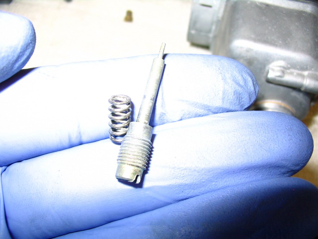
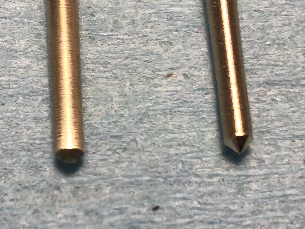
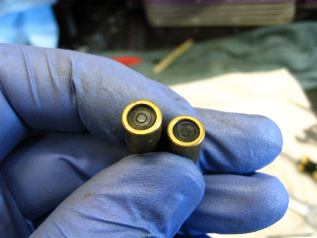
Always inspect your needle for wear. Notice the worn down tip of the old one on the left from years of pushing down the spring on the accelerator pump vs the pointed tip on the new one on the right. Both are V-5 needles.
Photo courtesy of Dan Eberhardt.
Always inspect your needle for wear. Notice the worn down tip of the old one on the left from years of pushing down the spring on the accelerator pump vs the pointed tip on the new one on the right. Both are V-5 needles.
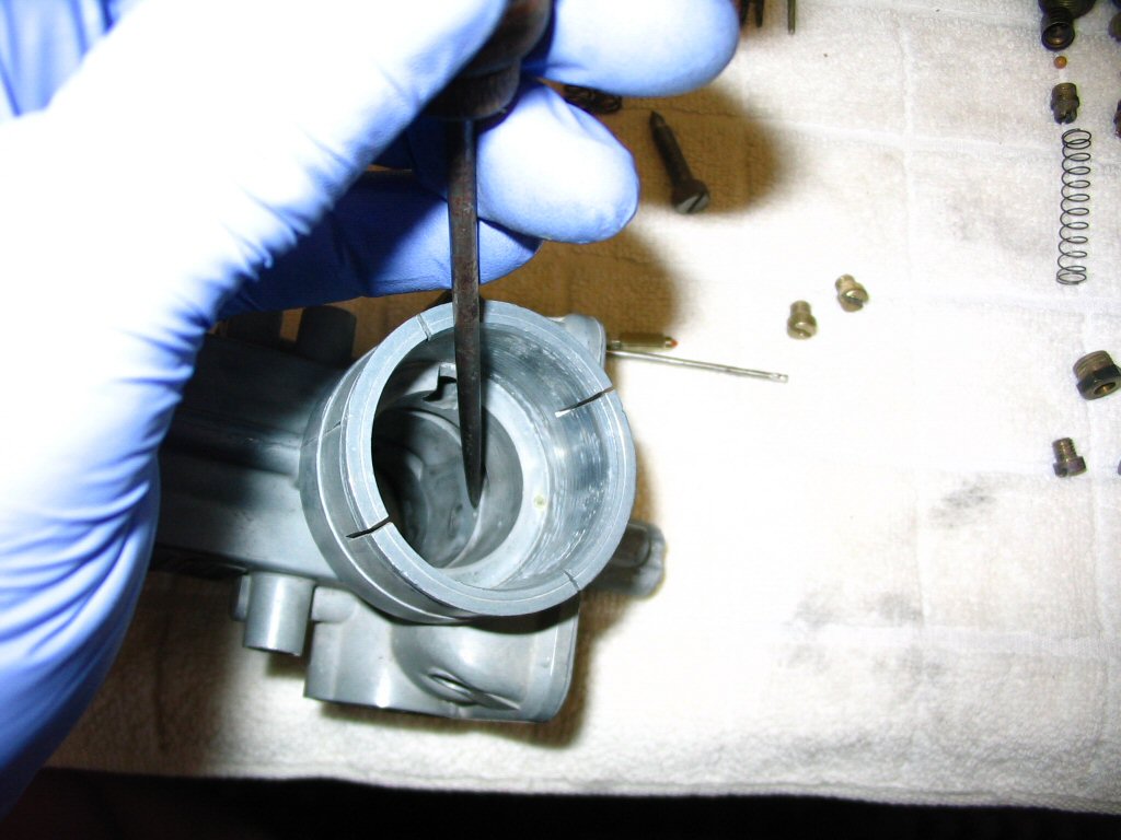
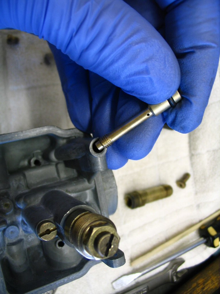
Insert the top of the tapered needle into the bottom of the slide and push it through. I do it this way so that I avoid any potential damage to the tapered needle.
Insert the slide complete with tapered needle into the body of the carburetor. Notice that the large flat area of the slide must face the intake manifold, not the air filter.
Now place the carburetor top complete with spring onto the top of the carburetor. Note that the cable adjuster is positioned nearest the intake manifold, not the air filter.
Hold the top down on top of the carburetor body and screw the top in place. DO NOT OVERTIGHTEN THESE BOLTS! They only take a light snug and are far too easy to strip. Be careful. I will also reemphasize, hold the top in its finished position and then screw the bolts in place. That is, don't use the bolts to pull the top into position.
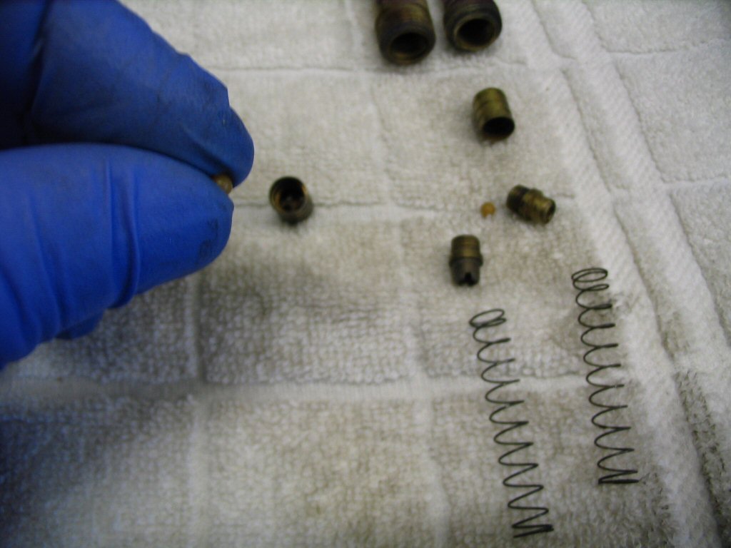
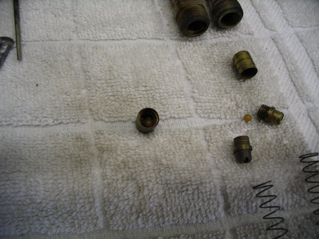
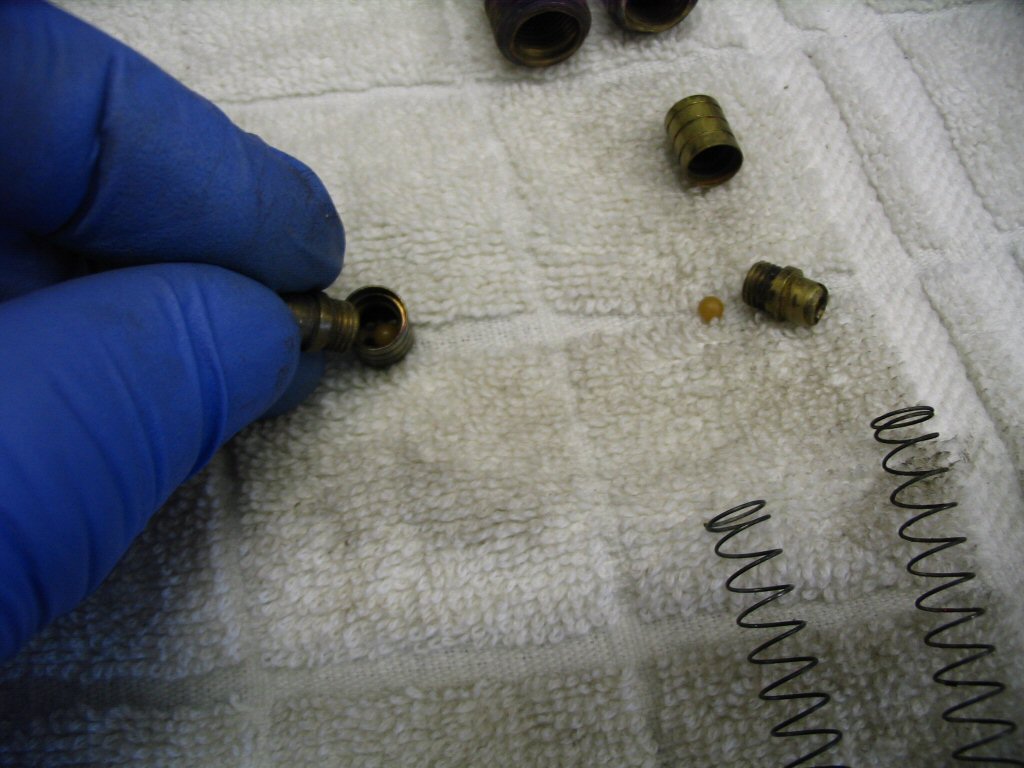
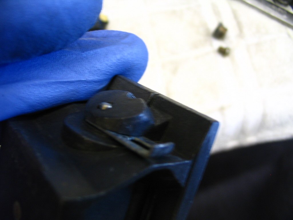
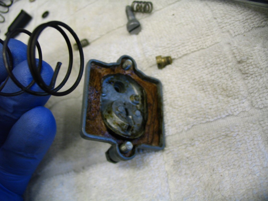
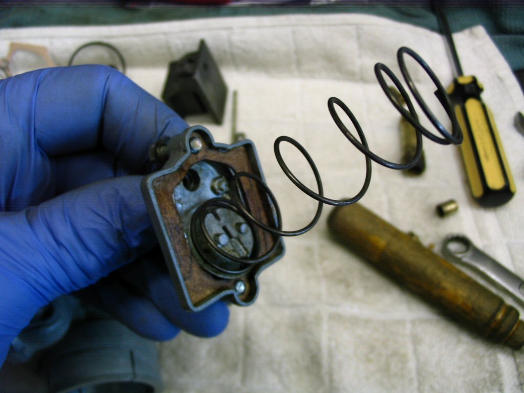
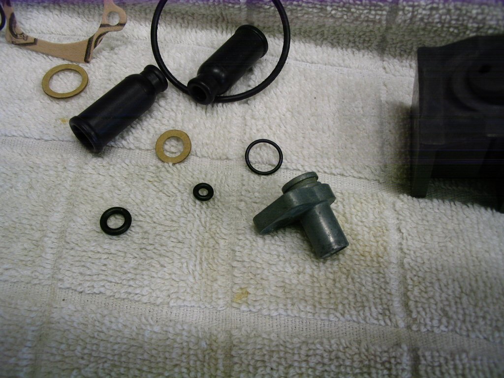
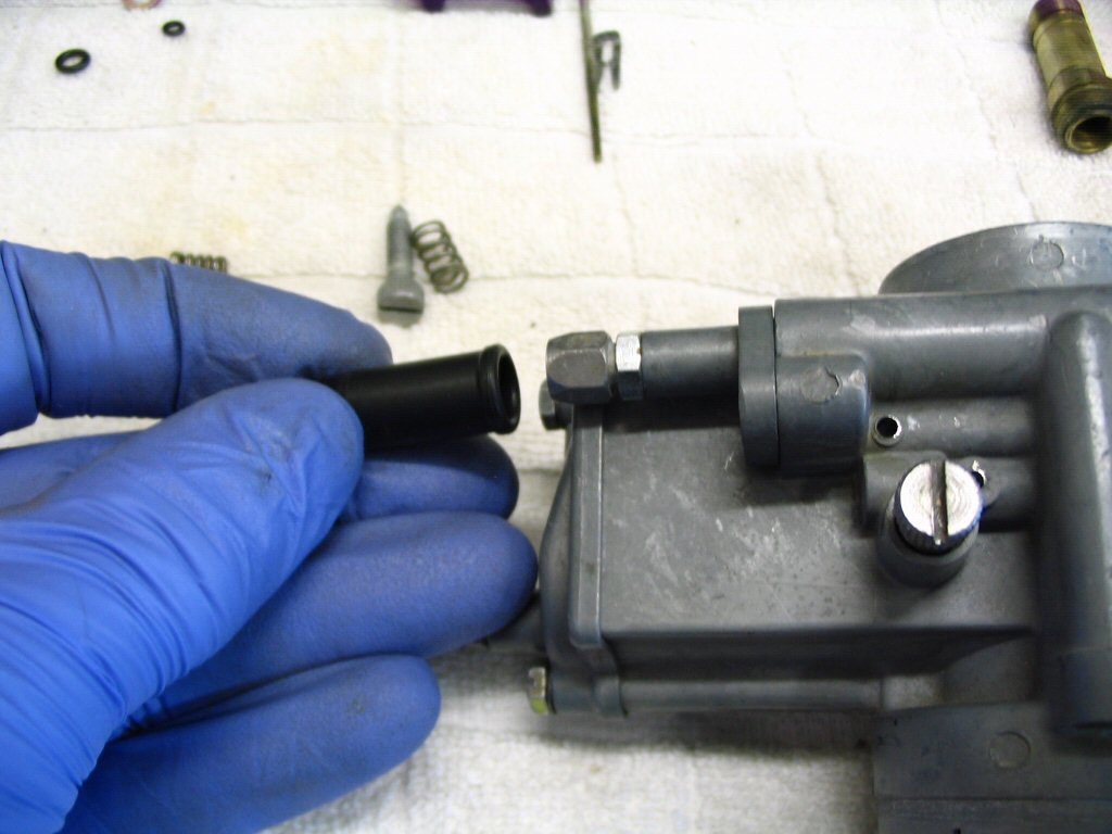
This is the sealing surface of the choke (enricher) plungers. New plungers have a flat sealing surface that has not been indented by years of constant spring pressure. While these may function fine, I will not reuse them. New ones are inexpensive and easily replaced. Adam S. recommends the following technique to extend the life of the plungers: One trick that I use, and it works fine, is to remove the rubber plug from the choke plunger, using a small dental pick. Flip the rubber piece over and you'll have a nice new sealing surface.
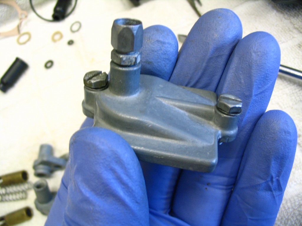
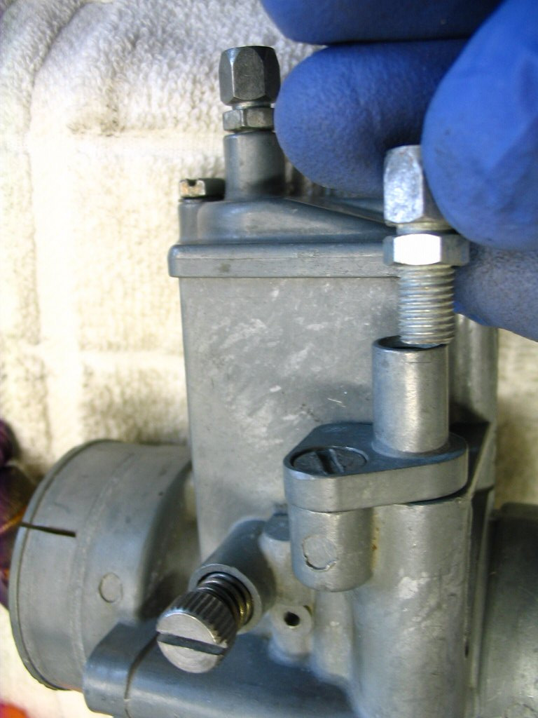
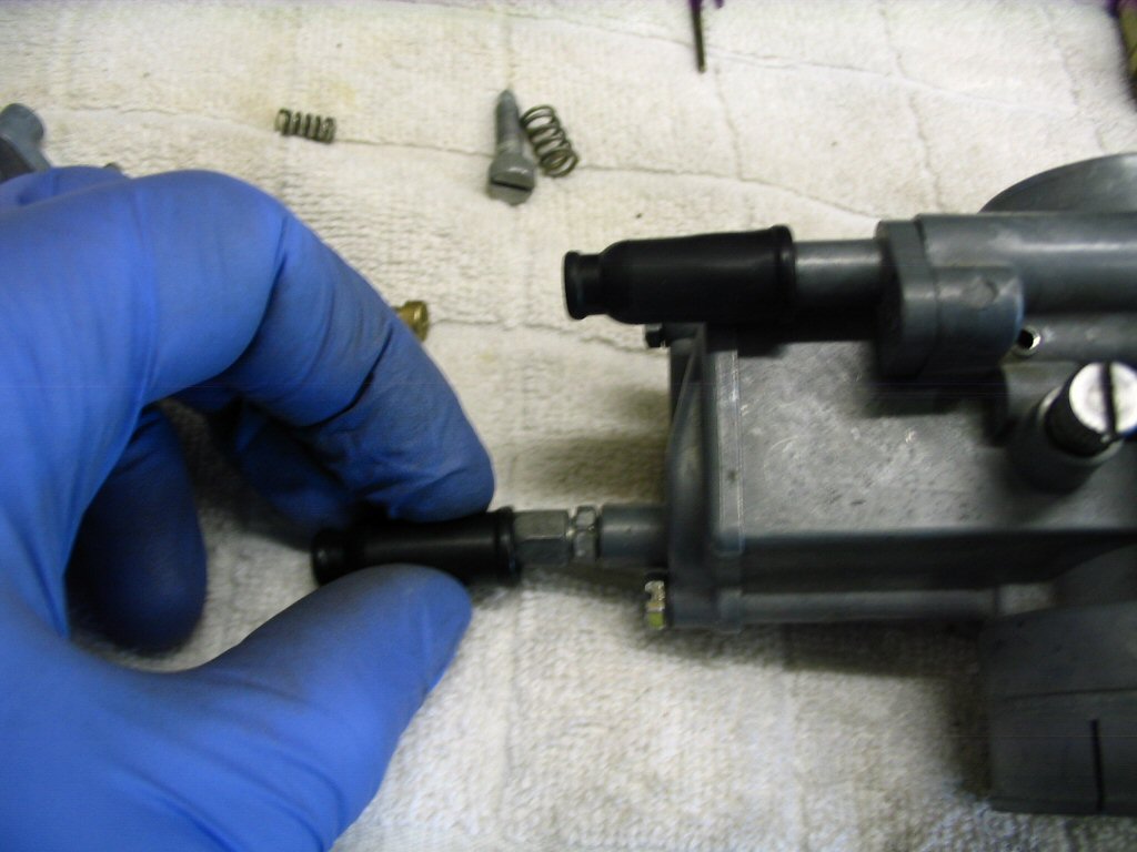
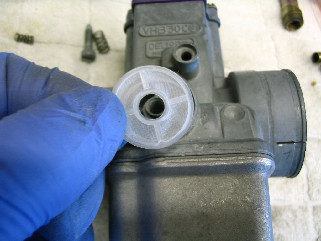
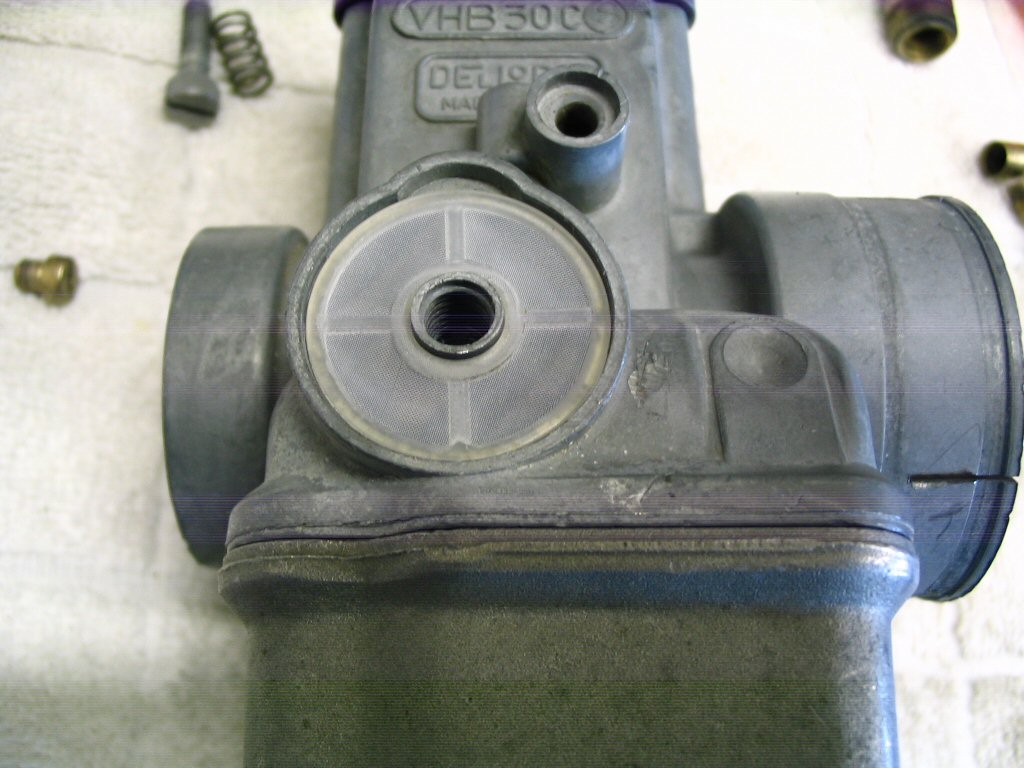
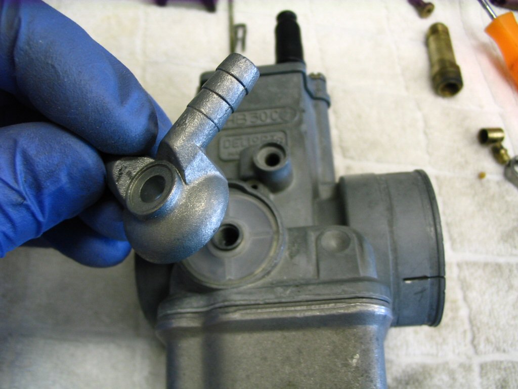
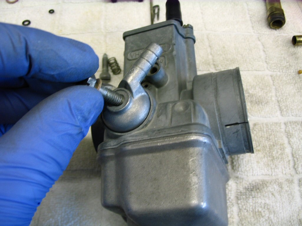
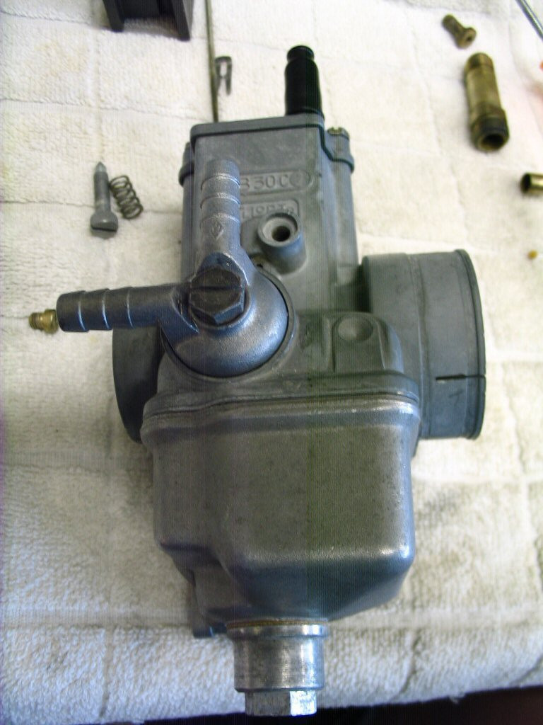
And tighten to secure. You'll want to snug the bolt, but not over tighten. If fuel leaks from this location when you hook up the tank, check a couple things. (1) Did you fit a new plastic filter? If not fit one. (2) Is the banjo fitting bottoming out before it makes sealing contact with the plastic filter? I had one that did this. Drove me crazy until I figured it out. I fit a new banjo and it sealed immediately. Do be careful not to over tighten these bolts. The threads are somewhat easily striped. It is much easier (and cheaper) to replace the plastic filter and banjo than to deal with buggered threads. JUST ANOTHER QUARTER TURN IS NOT YOUR FRIEND!