Brackets to mount a Tonti timing cover in a loop frame
Moto Guzzi V700, V7 Special, Ambassador, 850 GT, 850 GT California, Eldorado, and 850 California Police models
Created:
Updated:
Thanks to Mike Tiberio who posted this information on the old Yahoo! Loopframe_Guzzi news group (which has now moved to Groups.io). In Mike's own words:
Please see the followup information at the bottom of this page.
If your like me you like the look of a tonti motor complete with pancake alternator in a loop frame. I like the open air look where the generator (or GF alternator conversion goes). I had the added incentive of making these brackets as I'm making an Eldorado Automatic this winter,and didn't want to have to engineer an electric ATF pump. I posted a scan of my plans that I sent to my machinist a few weeks ago. I got the brackets back this week, and have sized them with a spare timing cover. I'll only know if I got the dimension right when I put the entire drivetrain in and check the drive shaft alignment, but this check tells me I got the side to side dimensions right.
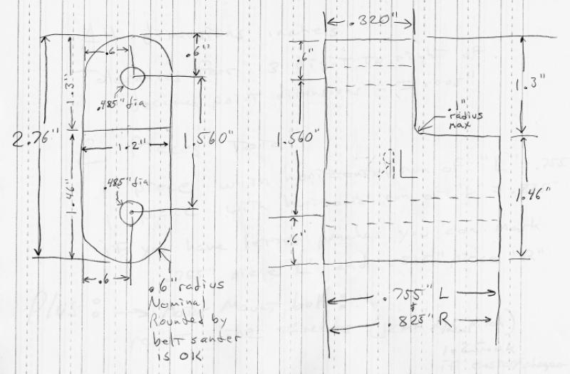
Motor Mount Plans: Hanger bracket to allow motor with tonti timing cover to be mounted into loop frame without welding.
Photo courtesy of Mike Tiberio.
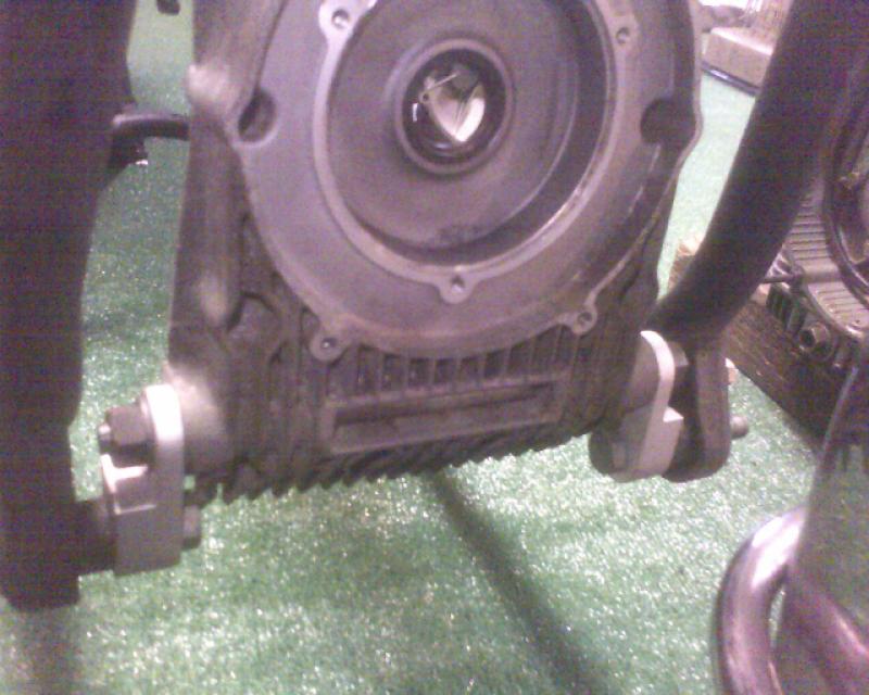
Tonti Timing Cover Hanger Bracket 1.
Photo courtesy of Mike Tiberio.
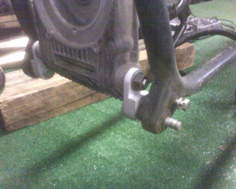
Tonti Timing Cover Hanger Bracket 2.
Photo courtesy of Mike Tiberio.
Question from Gregory Bender:
It is my understanding that the Tonti alternator cover will hit the front fender upon full fork compression? I don't have any direct experience with this, however, so I may be recalling incorrect information, etc. Can you shed some light on this?
My understanding is, if you do nothing, the fender (or perhaps more accurately the fender brace) will hit the cover. Once again I've been told that all that is necessary is to rotate the lower front fender mount downward. This would require drilling 2 new holes, and leave 2 holes to be plugged, so a purist might not want to do it, but then a purist wouldn't be mounting a tonti motor in a loop frame anyway.
Now if you look at a California II front fender (granted tonti frame), they have a flat spot hammered into the fender, I hope that isn't necessary as mine is chromed and might flake.
Other issue. I have heard of folks using a welded spool onto the loop frame to do what I have done with my links. While I was jigging all this up, I put a tonti drive train in my loop frame, and installed only the rear trans mount and battery tray. I supported the front of the motor with a jack. I figured I'd use the alignment of the fins with the lower rail (from the rear of the oil pan forward up to the 3rd oil pan bolt they are parallel nicely), to get the output shaft alignment correct. I wasn't happy with that method, and I wish I had paid attention to the original output shaft alignment relative to the swing arm pivot, but never did. I figure to minimize stress on the u-joint, the output shaft of the trans should point directly dead center to the swing arm pivot (I mean centerline to centerline). Achieving this alignment, I realized that the front tonti motor mount hole did not align with the crotch in the loop frame (this crotch is formed when the factory welds the front motor mount onto the loop). Now to bring this story full circle and make a long story longer, back to the spool weld jobs. If the anecdotal evidence on fender clearance is based on folks using the welded spool method, their clearance might be different than mine. because I believe my motor mount bolt is lower than theirs... whew.
Now if I wasn't so lazy I get a tonti drivetrain back into the frame now that I have my links, but I'm waiting till I have the motor and trans done, so I hopefully only have to do it once...
I invested $155 in my links, that included shortening and rethreading the front motor mount bolt (actually not a bolt, has a nut on each end). I'd be thrilled if someone would key up my plans (in the photo section) with the emachineshop.com cad software, so we could get an independent quote on these, because if I blew the dimensions, I'm looking at shelling out at least another $140...
Finally got my convert motor and trans done and bolted together. Got them up into the loop frame tonight, and finally got to check out how my new front motor hanger brackets did as far as output shaft alignment. I'm pleased to report that it looks great.
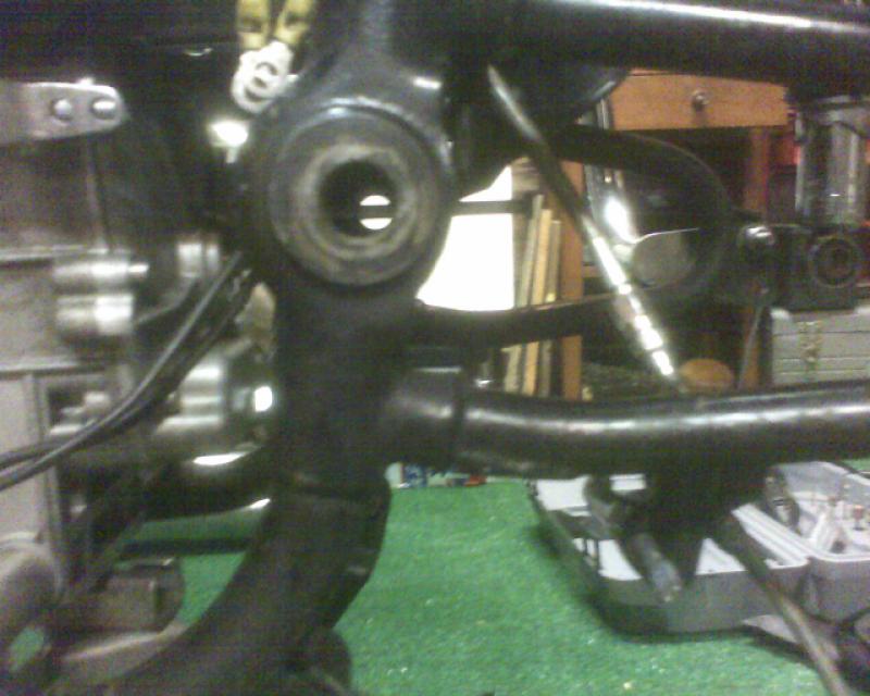
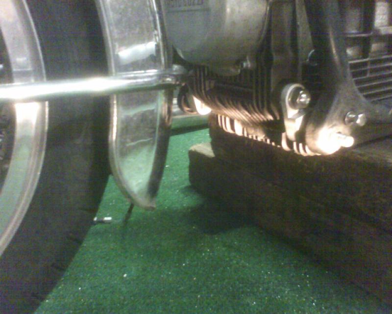
The first shot show the alignment. the convert output shaft is hollow and threaded. I screwed a long bolt into it, and the picture shows how the output shaft axis is co-planer with the swing arm pivot axis (the bolt exactly splits the pivot pin holes). this is key to minimize stress on the u-joint.
Output shaft alignment: I threaded a long bolt into the convert output shaft. You can see it aims dead center to the swing arm pivot.
Photo courtesy of Mike Tiberio.
This second shot shows the front timing cover with the alternator cover installed. It shows how I'll have to lower the lower fender mount as a minimum to get the fender to clear the alternator cover.
Hanger bracket, fender, alternator cover: A shot of the tonti motor to loop frame hanger brackets, and the needed fender bracket re-route.
Photo courtesy of Mike Tiberio.
Also if you look at my plans, you'll notice the mounts are asymmetrical side to side. I was a little concerned about this, but the result is my motor sits dead center in the frame, so I'd say that at least for my frame it was the right way to go. My machinist, JVE of Greenville South Carolina, made these brackets for me, and could no doubt make some for you.
Updated information from Mike Tiberio about the design and how it has worked out over time. In Mike's own words:
The original one piece design was ell shaped, and had a stress riser and cracked in the original Aluminum. I had them remade in tool steel. Same result.
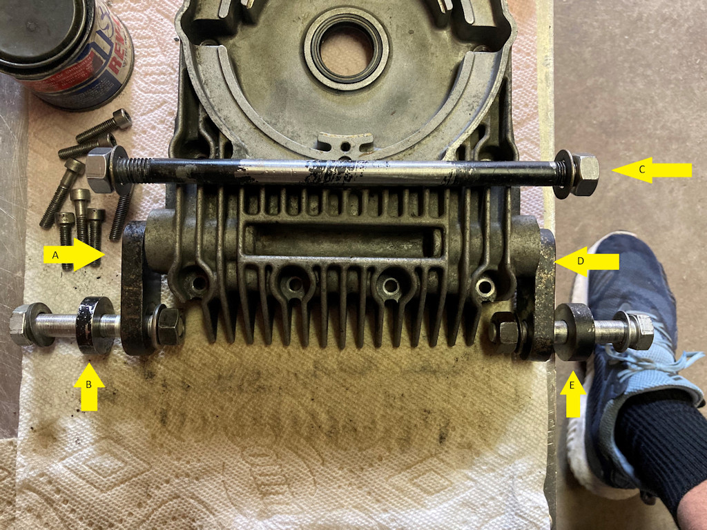
I finally decided to make the vertical component one piece and allow it to flex separately from the spacer function. The new hanger is 2 pieces per side, a simple link (plate with 2 holes) and a cylindrical spacer (more like a fat washer). For strength the link is tool steel, and for weight savings, the spacer is aluminum. In the attached diagram I have labeled the parts of interest to make this work.
A = Right side link (left in picture). Steel. Both links are 0.43 inch wide and the hole diameters and center to center dimension can be gleaned from my original plans.
B = Right side spacer. Aluminum. This one is 0.395 inch wide, outer diameter nominal, look at radius stated in plans.
C = Cross Bolt (threads both ends). Stainless Steel. This bolts the links on each end to the front tonti timing cover.
D = Left side link. Steel. This one is also 0.43 inch wide. Hole diameters and locations, see above.
E = Left side spacer. Aluminum. This one is 0.325 inch wide. OD as above.
The bolts used to clamp the link and spacer to the loop frame lug if inserted from the outside need to be of a proper length. I removed the vertical fin closest to the nut as one got broken off any way and it gives you a bit more room to work with. Running bolts from outside in rather than the other way makes lining up all the bolts, etc easier, but bolt length is critical (or have some washers handy).